- Hinweis auf planmäßige Wartung: Diese Seite wird auf Grund von Wartungsarbeiten in der Zeit von 3:00 21/4/2024 bis 0:00 (CET) 22/4/2024 nicht verfügbar sein. Wir entschuldigen uns vielmals für die Unannehmlichkeiten.
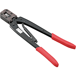
JL05 Contact Crimper
Klicken Sie auf dieses Bild, um es zu vergrößern.
Klicken Sie auf dieses Bild, um es zu vergrößern.
- Mengenrabatt
- IP67

● Tools to crimp the contact for JL05 and tools to extract the contact.
● Applicable tools vary depending on the contact size.
Teilenummer
Hier finden Sie die Teilenummern
zu dem gesuchten Artikel
Spezifikationen
| Model Number | Type |
| JCT-16128-3 | Tool Body |
| MS22520-1-01 | |
| CT170-11C-JL05 | |
| CT170-11B-JL05 | |
| CT170-11-JL05 | |
| CT150-2C-JL05 | |
| CT150-2B-JL05 | |
| L-JL05-8 | Locator |
| JP-JL05-12 | |
| CIET-16 | Insertion Tool |
| JIET-DXC-20 | Insertion / Extracting Tool |
| JET-GTC-8 | Extracting Tool |
| JET-GTC-K15 | |
| ET-JL05-16 | |
| ET-JL05-20-2 | |
| ET-JL05-20-3 |
Also, only this product is a stocked product.
Weitere Informationen
Tool Application Table
| Contact Size | Compatible Wire (AWG) | Tool Body | Locator | Insertion Tool | Extracting Tool |
| #8 | #10 ~ 8 | JCT-16128-3 | L-JL05-8 | — | JET-GTC-8 |
| #12 ~ 10 | — | ||||
| #12 | #16 ~ 12 | MS22520-1-01 | JP-JL05-12 | — | JET-GTC-K15 |
| #16 | #16 ~ 14 | CT170-11C-JL05 | — | — | ET-JL05-16 |
| #20 ~ 16 | CT170-11B-JL05 | — | CIET-16 | ||
| #24 ~ 20 | CT170-11-JL05 | — | — | ||
| #20 | #18 ~ 22 | CT150-2C-JL05 | — | JIET-DXC-20 | ET-JL05-20-2 ET-JL05-20-3 (dedicated for female contacts) |
| #22 ~ 26 | CT150-2B-JL05 | — |
Teilenummer
|
|---|
| CT150-2C-JL05 |
| ET-JL05-16 |
| JP-JL05-12 |
| MS22520-1-01 |
| Teilenummer |
Standard-Stückpreis
| Mindestbestellmenge | Mengenrabatt | RoHS | Contact Size | Compatible Wire Size (AWG) | Product Classification | |
|---|---|---|---|---|---|---|---|---|
1,373.37 € | 1 | Verfügbar | 5 Arbeitstage | - | #20 | 18 ~ 22 | Crimping Tool | |
158.44 € | 1 | Verfügbar | 5 Arbeitstage | 10 | #16 | 14 ~ 24 | Extraction Tool | |
250.27 € | 1 | 5 Arbeitstage | - | #12 | 8 ~ 12 | Locator | ||
498.17 € | 1 | 7 Arbeitstage | - | #12 | 16 ~ 12 | Crimping Tool |
Loading...
Crimp Type / Bayonet Lock Waterproof Large Connector (JL05)
Material / Finish
| Item | Material / Finish |
|---|---|
| Shell | Aluminum Alloy / Galvanizing (Blackish interference color trivalent chromate film) |
| Base Insulator | Synthetic Resin |
| Cover Insulator | Synthetic Resin |
| Contact | Copper Alloy / Silver Plating |
| Retaining Ring | Copper Alloy / Galvanizing (Blackish interference color trivalent chromate film) |
| O-ring | Synthetic Rubber |
| Earth Lug | Copper Alloy / Silver Plating |
| Item | Material / Finish |
|---|---|
| Coupling Nut, Barrel | Aluminum Alloy / Galvanizing (Blackish interference color trivalent chromate film) |
| Base Insulator | Synthetic Resin |
| Cover Insulator | Synthetic Resin |
| Contact | Copper Alloy / Silver Plating |
| Retaining Ring | Copper Alloy / Galvanizing (Blackish interference color trivalent chromate film) |
| Stop Ring | Stainless Steel |
| Wave Spring | Stainless Steel |
| Earth Lug | Copper Alloy / Silver Plating |
| Item | Material / Finish |
|---|---|
| End Bell Body, Ground Nut | Aluminum Alloy / Galvanizing (Blackish interference color trivalent chromate film) |
| Pushing | Synthetic Rubber (Black) |
| Sleeve | Aluminum Alloy / Galvanizing (Blackish interference color trivalent chromate film) |
| O-ring | Synthetic Rubber |
| Hex Hole Locking Screw | Steel / Galvanized (M3 ×0.5) |
| Item | Material / Finish |
|---|---|
| End Bell Body | Aluminum Alloy / Galvanizing (Blackish interference color trivalent chromate film) |
| Hex Hole Locking Screw | Steel / Galvanized (M3 ×0.5) |
About Compatibility, Electrical and Mechanical Properties
Common with NB01/CE01 series. JL05 connector is compatible with CE01 connectors and NB01 connectors.Contact Arrangement Diagram
| Number of Contacts | 4 | 5 | 7 | 7 | 8 |
|---|---|---|---|---|---|
| Arrangement No. | 22-22 | 18-11 | 20-15 | 24-10 | 22-23 |
| Contact Size | #8 | #12 | #12 | #8 | #12 |
| Contact Arrangement (Note 1) (Note 2) |
 |
 |
 |
 |
 |
| Rating Classification | A | A | A | A | D (4), A (Others) |
| Number of Contacts | 10 | 17 | 19 | 19 | 24 |
|---|---|---|---|---|---|
| Arrangement No. | 18-1 | 20-29 | 18-19A | 22-14 | 24-28 |
| Contact Size | #16 | #16 | #20 | #16 | #16 |
| Contact Arrangement (Note 1) (Note 2) |
 |
 |
 |
 |
 |
| Rating Classification | A (3, 5, 6, 8), INST (Others) | A | INST | A | INST |
| Number of Contacts | 30 | 37 | 52 | 73 |
|---|---|---|---|---|
| Arrangement No. | 20-30A | 28-21 | 24-52A | 28-73A |
| Contact Size | #20 | #16 | #20 | #20 |
| Contact Arrangement (Note 1) (Note 2) |
 |
 |
 |
 |
| Rating Classification | INST | A | INST | INST |
(Note 1) View from the male (pin) connector coupling surface.
(Note 2) The ○ in the arrangement table shows the earth terminals (for protection of terminal connections).
Panel Cut Size Drawing
| Compatible Shell Size |
φA ±0.5 |
φB +0.2 -0 |
C ±0.13 |
Mounting Screws (Reference) | Rear Mounting Panel Thickness Limit |
|
|---|---|---|---|---|---|---|
| Inch Screws | Metric Screws | |||||
| 18 | 30.2 | 3.3 | 26.97 | #4-40 | M3 | 3.0 or less |
| 20 | 34.9 | 3.3 | 29.36 | #4-40 | M3 | |
| 22 | 36.6 | 3.3 | 31.75 | #4-40 | M3 | |
| 24 | 39.7 | 4.3 | 34.92 | #6-32 | M4 | |
| 28 | 46.1 | 4.3 | 39.67 | #6-32 | M4 | |
Combination Method
Combination Example
Grundlegende Informationen
| Applicable Type | JL05 Connector |
|---|
Konfigurieren
Basiseigenschaften
-
Contact Size
- #12
- #16
- #20
-
Compatible Wire Size(AWG)
-
Product Classification
- Crimping Tool
- Extraction Tool
- Locator
Filtern nach vsl. Lieferzeit
-
- Alle Produkte
- 5 Tage oder weniger
- 7 Tage oder weniger
Optionale Eigenschaften
- Die Spezifikationen und Maße einiger Teile sind evtl. nicht vollständig enthalten. Genaue Details siehe Herstellerkataloge .
Technischer Support
Bezahlverfahren


On-Demand-Fertigung
Zertifikate


Copyright © MISUMI Corporation All Rights Reserved.