- Zylinder-Innen-Ø: D(Ø)
- 25
- Hub: L(mm)
- 30
- Operating Pressure(MPa)
- Specifications
- Support bracket
- Port thread type
- Auto Switch
- Lead Wire Length(m)
- 5
- Number of Switches
- 2
- Ausführung
- CAD
- 2D
- 3D
- Vsl. Versanddatum
- Alle
- Innerhalb von 26 Werktagen
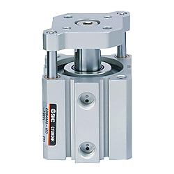
C (D) QM, Kompaktzylinder mit Führungsstange (CDQMB25-30-M9BZ)


Produktdaten
Compact Cylinder, Guide-Rod Type CQM Series Specifications
Model Number Notation
Model Number Notation
Specifications
| Tube Internal Diameter (mm) | 12 | 16 | 20 | 25 | 32 | 40 | 50 | 63 | 80 | 100 |
|---|---|---|---|---|---|---|---|---|---|---|
| Model | Pneumatic (non-lube) type | |||||||||
| Action | Double acting, single rod | |||||||||
| Applicable fluids | Air | |||||||||
| Proof pressure | 1.5 MPa | |||||||||
| Maximum operating pressure | 1.0 MPa | |||||||||
| Minimum operating pressure | 0.12 MPa | 0.1 MPa | ||||||||
| Ambient and fluid temperature | Without auto switch: -10°C to +70°C (No freezing) With auto switch: -10°C to +60°C (No freezing) | |||||||||
| Cushion | Rubber bumper at both ends | |||||||||
| Stroke length tolerance | +1.0 mm* 0 | |||||||||
| Mounting | Through-holes | |||||||||
| Piston speed | 50 to 500 mm/s | 50 to 300 mm/s | ||||||||
- *Stroke length tolerance does not include the amount of bumper change.
Standard stroke
| Bore size (mm) | Standard stroke (mm) |
|---|---|
| 12, 16 | 5, 10, 15, 20, 25, 30 |
| 20, 25 | 5, 10, 15, 20, 25, 30, 35, 40, 45, 50 |
| 32, 40 | 5, 10, 15, 20, 25, 30, 35, 40, 45, 50, 75, 100 |
| 50, 63, 80, 100 | 10, 15, 20, 25, 30, 35, 40, 45, 50, 75, 100 |
Structural drawing
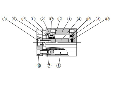
ø12 to ø25 (12‑ to 25‑mm bore size)
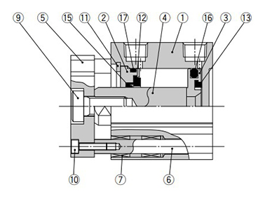
ø32 to ø100 (32‑mm to 100‑mm bore size)

ø50 to ø100 (50‑mm to 100‑mm bore size)
Component Parts
| Number | Description | Material | Note |
|---|---|---|---|
| 1 | Cylinder tube | Aluminum alloy | Hard anodized |
| 2 | Collar | Aluminum alloy | ø12 to ø40 (12‑mm to 40‑mm bore size) Anodized |
| Aluminum alloy casted | ø50 to ø100 (50‑mm to 100‑mm bore size) Chromated, coated | ||
| 3 | Piston | Aluminum alloy | - |
| 4 | Piston rod | Stainless steel | ø12 to ø25 (12‑mm to 25‑mm bore size) |
| Carbon steel | ø32 to ø100 (32‑mm to 100‑mm bore size) Hard chrome plated | ||
| 5 | Plate | Aluminum alloy | Anodized |
| 6 | Guide rod | Stainless steel | - |
| 7 | Bushing | Resin/Copper alloy (Multiple layers) | - |
| 8 | Bushing | Resin/Copper alloy (Multiple layers) | ø50 to ø100 (50‑mm to 100‑mm bore size) |
| 9 | Hexagon socket head cap screw | Carbon steel | Zinc chromated |
| 10 | Hexagon socket head cap screw | Carbon steel | Zinc chromated |
| 11 | Retaining ring | Carbon tool steel | Phosphate coated |
| 12 | Bumper A | Urethane | - |
| 13 | Bumper B | Urethane | - |
| 14 | Magnet | - | - |
| 15 | Rod seal | NBR | - |
| 16 | Piston seal | NBR | - |
| 17 | Gasket | NBR | - |
Compact Cylinder, Guide-Rod Type CQM Series Example Dimensions
ø12 to ø25 (12‑ to 25‑mm bore size) dimensional drawing
(Unit: mm)
| Bore size (mm) | Stroke range (mm) | Without auto switch | With auto switch | EA | EB | F | HA | OA | HB | IA | IB | ||
|---|---|---|---|---|---|---|---|---|---|---|---|---|---|
| A | B | A | B | ||||||||||
| 12 | 5 to 30 | 26.5 | 17 | 31.5 | 22 | 25 | 24 | 5 | M3 × 0.5 | M4 × 0.7 | 3 (0 to +0.2) | 32 | 31.5 |
| 16 | 5 to 30 | 26.5 | 17 | 31.5 | 22 | 29 | 28 | 5 | M3 × 0.5 | M4 × 0.7 | 3 (0 to +0.2) | 38 | 37 |
| 20 | 5 to 50 | 32 | 19.5 | 42 | 29.5 | 36 | 34 | 5.5 | M4 × 0.7 | M6 × 1.0 | 4 (0 to +0.2) | 47 | 45.5 |
| 25 | 5 to 50 | 35.5 | 22.5 | 45.5 | 32.5 | 40 | 38 | 5.5 | M5 × 0.8 | M6 × 1.0 | 5 (0 to +0.2) | 52 | 50.5 |
(Unit: mm)
| Bore size (mm) | KA | KB | L | M | N | OB | Q | RA | RB | T | V | W |
|---|---|---|---|---|---|---|---|---|---|---|---|---|
| 12 | 10 ± 0.1 | 7.1 | 3.5 | 15.5 | 3.5 | 6.5 | 7.5 | 7 | 4 | 0.5 | 14.9 | 6 |
| 16 | 14 ± 0.1 | 9.9 | 3.5 | 20 | 3.5 | 6.5 | 7.5 | 7 | 4 | 0.5 | 20 | 6 |
| 20 | 17 ± 0.1 | 12 | 4.5 | 25.5 | 5.4 | 9 | 9 | 10 | 7 | 1 | 26 | 8 |
| 25 | 22 ± 0.1 | 15.6 | 5 | 28 | 5.4 | 9 | 11 | 10 | 7 | 1 | 30 | 8 |
Note) For the following bore/stroke sizes, the through-hole is threaded: Standard without auto switch: ø12 (12‑mm bore size) and ø16 (16‑mm bore size) 5 stroke; ø20 (20‑mm bore size) 5 to 15 stroke; ø25 (25‑mm bore size) 5 and 10 stroke. Built-in magnet with auto switch: ø20 (20‑mm bore size) 5 stroke.
Weitere Informationen
Grundlegende Informationen
Der CQM ist ein Kompaktzylinder mit Führungsstange und Platte. Die Serie ist erhältlich in den Kolbengrößen 12, 16, 20, 25, 32, 40, 50, 63, 80 und 100 mm mit den gleichen Montageabmessungen wie der CQ2. Dank Führungsstange und Platte können Werkstücke direkt montiert werden. Die Serie CQM hat im Vergleich zu Serie CQ2K die vierfache Querlastbeständigkeit und eine Verdrehtoleranz von ±0.2°.
Achtung
- See catalog for specification details.
- Product pictures are representations. CAD data is not supported for some model numbers.