- Zulässige Flüssigkeit
- Betriebsumgebung
- Schalterausführung
- Verbindungsausführung
- Rc (R)
- Rc
- Rohrleitungsgewinde, Nenn-Ø
- Öffnungs-Ø(mm)
- 4
- Spannung
- Dichtungsmaterialien
- Verbindungsleitung Ausgang Richtung
- Option
- Grundwerkstoff
- Befestigungselement
- Funktionen
- Verbindungsleitung elektrischer Eingang
- Scheinleistung(VA)
- Ausführung
- CAD
- 2D
- 3D
- Vsl. Versanddatum
- Alle
- Innerhalb von 26 Werktagen
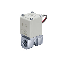
Direkt betätigtes 2-Wege-Magnetventil, Serie VX21 / 22 / 23 (VX222AZ1VXB)


Produktdaten
Direct Operated 2 Port Solenoid Valve VX21/VX22/VX23 Series Features
| Valve Specifications | Valve Construction | Direct operated poppet | |
|---|---|---|---|
| Withstand Pressure | 2.0 MPa (resin body type: 1.5 MPa) | ||
| Body Material | Aluminum, resin, C37, Stainless steel | ||
| Seal Material*3 | NBR, FKM | ||
| Enclosure | Dustproof, water-jet-proof type (IP65)*1, *4 | ||
| Environment | Locations without corrosive or explosive gases | ||
| Coil Specifications | Rated Voltage | AC | 100 V AC, 200 V AC, 110 V AC, 230 V AC, (220 V AC, 240 V AC, 48 V AC, 24 V AC)*2 |
| DC | 24 V DC, (12 V DC)*2 | ||
| Allowable Voltage Fluctuation | ±10% of rated voltage | ||
| Allowable Leakage Voltage | AC | 5% or less of rated voltage | |
| DC | 2% or less of rated voltage | ||
| Coil Insulation Type | Class B, class H | ||
*1 Electrical entry "Faston" type terminal is IP40 compliant.
*2 Voltage inside () indicates special voltage.
*3 Refer to X332 regarding seal material / EPDM.
*4 See glossary for information on protection grades. Contact the SMC support center regarding use in locations that require water resistance.
- *Be sure to read the individual product precautions before use.
For Air Single Unit Specifications
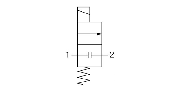
N.C. type flow passage symbol
N.C. type external appearance
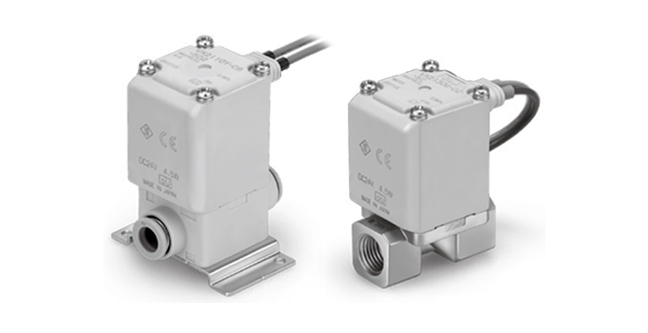
Aluminum Body Type
| Size | Port Size | ø(Orifice Diameter mm)*1 | Model | Flow Rate Characteristics*2 | Maximum Operating Pressure Differential MPa *4 | Maximum System Pressure MPa *4 | Weight*3 (g) | ||
|---|---|---|---|---|---|---|---|---|---|
| C [dm3/(s·bar)] | b | Cv | |||||||
| 1 | 1/8, 1/4 | 2 | VX210 | 0.63 | 0.63 | 0.23 | 1.0 | 1.0 | 220 |
| 3 | 1.05 | 0.68 | 0.41 | 0.6 | 220 | ||||
| 5 | 2.20 | 0.39 | 0.62 | 0.2 | 220 | ||||
| 2 | 1/4, 3/8 | 4 | VX220 | 1.90 | 0.52 | 0.62 | 1.0 | 340 | |
| 7 | 3.99 | 0.44 | 1.08 | 0.15 | 340 | ||||
| 3 | 1/4, 3/8 | 5 | VX230 | 1.96 | 0.55 | 0.75 | 1.0 | 450 | |
| 8 | 5.67 | 0.33 | 1.58 | 0.3 | 450 | ||||
| 10 | 5.74 | 0.64 | 2.21 | 0.1 | 450 | ||||
| 1/2 | 10 | 8.42 | 0.39 | 2.21 | 0.1 | 470 | |||
Resin Body Type (Built-In One-Touch Fitting)
| Size | Port Size | ø(Orifice Diameter mm)*1 | Model | Flow Rate Characteristics*2 | Maximum Operating Pressure Differential MPa *4 | Maximum System Pressure MPa *4 | Weight*3 (g) | ||
|---|---|---|---|---|---|---|---|---|---|
| C [dm3/(s·bar)] | b | Cv | |||||||
| 1 | ø6 mm | 2 | VX210 | 0.82 | 0.44 | 0.23 | 1.0 | 1.0 | 220 |
| 3 | 1.25 | 0.34 | 0.35 | 0.6 | 220 | ||||
| 5 | 1.45 | 0.43 | 0.40 | 0.2 | 220 | ||||
| ø8 mm | 2 | 0.82 | 0.44 | 0.23 | 1.0 | 220 | |||
| 3 | 1.81 | 0.40 | 0.41 | 0.6 | 220 | ||||
| 5 | 2.11 | 0.32 | 0.56 | 0.2 | 220 | ||||
| 2 | ø8 mm | 4 | VX220 | 1.69 | 0.40 | 0.47 | 1.0 | 340 | |
| 7 | 3.14 | 0.34 | 0.84 | 0.15 | 340 | ||||
| ø10 mm | 4 | 1.68 | 0.49 | 0.50 | 1.0 | 340 | |||
| 7 | 3.54 | 0.36 | 0.90 | 0.15 | 340 | ||||
| 3 | ø10 mm | 5 | VX230 | 2.50 | 0.44 | 0.70 | 1.0 | 460 | |
| 8 | 2.77 | 0.82 | 1.22 | 0.3 | 460 | ||||
| 10 | 5.69 | 0.46 | 1.54 | 0.1 | 460 | ||||
| ø12 mm | 5 | 2.50 | 0.44 | 0.70 | 1.0 | 460 | |||
| 8 | 2.56 | 0.88 | 1.38 | 0.3 | 460 | ||||
| 10 | 5.69 | 0.64 | 1.76 | 0.1 | 460 | ||||
*1: Orifice sizes are for reference. Check the flow rate characteristics (conversion Cv).
*2: There are variations in the flow rate characteristics of the product.
If high precision flow rate control is needed for the system, adjust accordingly by selecting an orifice that is at least 1.3 times larger in diameter and use a diaphragm, etc., on the secondary side of the solenoid valve.
*3: This is the grommet value. Add 10 g for conduit types, 30 g for DIN terminals, 60 g for conduit terminals respectively.
*4: See the glossary for details on the maximum operating pressure differential and the maximum system pressure.
Fluid Temperature and Ambient Temperature
- Fluid temperature: -10 to +60°C *: Dew point temperature: -10°C or less
- Ambient temperature: -20 to +60°C
Valve Leakage Rate
Internal Leakage
| Seal material*2 | Leakage Rate (Air)*1 |
|---|---|
| NBR (FKM) | 1 cm3/min or less (aluminum body type) |
| 15 cm3/min or less (resin body type) |
Exterior Leakage
| Seal material*2 | Leakage Rate (Air)*1 |
|---|---|
| NBR (FKM) | 1 cm3/min or less (aluminum body type) |
| 15 cm3/min or less (resin body type) |
*1: The leakage rate is at an ambient temperature of 20°C.
*2: See the special options in the catalog for FKM sealing material.
*3: The leakage amount is at 20°C and with a differential pressure of 0.01 MPa or more. Contact the SMC support center when the differential pressure is less than 0.01 MPa.
- *Refer to the SMC catalog for other part numbers.
Weitere Informationen
Grundlegende Informationen
Für Industrieanwendungen, die 2/2-Wege-Magnetventile erfordern, bieten wir jetzt mit der Einführung unseres neuen, verbesserten VX2-Ventils optimierte Lösungen. Die neue Serie VX2 wurde im Rahmen unseres Programms zur ständigen Produktverbesserung entwickelt. Sie ist für Druckluft, mittleres Vakuum, Wasser oder Öl geeignet und bietet im Vergleich zu unserem Vorgängermodell VX21 erhebliche Leistungsvorteile.Die Ventile der neuen Serie VX2 bestechen nicht nur durch ihr modernes, helles Erscheinungsbild, sondern sind auch um ca. 10% kleiner und 30% leichter als die bisherigen Ventile. Gleichzeitig bietet sie jedoch bis zu 20% mehr Durchfluss. Dank der Verwendung elastischer Dämpfscheiben werden die Schaltgeräusche erheblich reduziert und eine neue Ausführung mit integrierten Steckverbindungen verringert den Anschlussaufwand. Darüber hinaus zeichnet sich die Serie VX2 durch eine verlängerte Lebensdauer und eine um bis zu 20VA reduzierte Leistungsaufnahme aus.
Achtung
- Bei Produktbildern kann es sich um repräsentative Bilder handeln. Einzelheiten finden Sie im Katalog.