JL05 Drip-Proof Cap (for Receptacle) (Teilenummern)
- Mengenrabatt
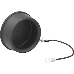
A drip-proof cap for preventing foreign body contamination and protecting the connected portion.

● To be used with the panel mount receptacles.
● It is IP55f when the cap is used.

Cap body (synthetic rubber), sleeve (copper alloy / tin plated)
String (nylon), crimp terminal (copper alloy / tin plated)

·Shares common outline drawing with NB01, CE01 series caps.
Teilenummer
Hier finden Sie die Teilenummern
zu dem gesuchten Artikel
JL05-24DC
Spezifikationen

| Model Number | Shell Size |
| JL05-18DC | 18 |
| JL05-20DC | 20 |
| JL05-22DC | 22 |
| JL05-24DC | 24 |
| JL05-28DC | 28 |
Teilenummer
|
|---|
| JL05-24DC |
| Teilenummer |
Standard-Stückpreis
| Mindestbestellmenge | Mengenrabatt | Compatible Shell Size | |
|---|---|---|---|---|---|
13.42 € | 1 | Verfügbar | 5 Arbeitstage | 24 |
Loading...
Crimp Type / Bayonet Lock Waterproof Large Connector (JL05)
Material / Finish
● Panel Mount Type / Contact
| Item | Material / Finish |
|---|---|
| Shell | Aluminum Alloy / Galvanizing (Blackish interference color trivalent chromate film) |
| Base Insulator | Synthetic Resin |
| Cover Insulator | Synthetic Resin |
| Contact | Copper Alloy / Silver Plating |
| Retaining Ring | Copper Alloy / Galvanizing (Blackish interference color trivalent chromate film) |
| O-ring | Synthetic Rubber |
| Earth Lug | Copper Alloy / Silver Plating |
● Straight Type / Contact
| Item | Material / Finish |
|---|---|
| Coupling Nut, Barrel | Aluminum Alloy / Galvanizing (Blackish interference color trivalent chromate film) |
| Base Insulator | Synthetic Resin |
| Cover Insulator | Synthetic Resin |
| Contact | Copper Alloy / Silver Plating |
| Retaining Ring | Copper Alloy / Galvanizing (Blackish interference color trivalent chromate film) |
| Stop Ring | Stainless Steel |
| Wave Spring | Stainless Steel |
| Earth Lug | Copper Alloy / Silver Plating |
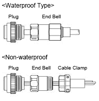
● End Bell (Waterproof Type)
| Item | Material / Finish |
|---|---|
| End Bell Body, Ground Nut | Aluminum Alloy / Galvanizing (Blackish interference color trivalent chromate film) |
| Pushing | Synthetic Rubber (Black) |
| Sleeve | Aluminum Alloy / Galvanizing (Blackish interference color trivalent chromate film) |
| O-ring | Synthetic Rubber |
| Hex Hole Locking Screw | Steel / Galvanized (M3 ×0.5) |
● End Bell (Non-waterproof Type)
| Item | Material / Finish |
|---|---|
| End Bell Body | Aluminum Alloy / Galvanizing (Blackish interference color trivalent chromate film) |
| Hex Hole Locking Screw | Steel / Galvanized (M3 ×0.5) |
About Compatibility, Electrical and Mechanical Properties
Common with NB01/CE01 series. JL05 connector is compatible with CE01 connectors and NB01 connectors.Contact Arrangement Diagram
| Number of Contacts | 4 | 5 | 7 | 7 | 8 |
|---|---|---|---|---|---|
| Arrangement No. | 22-22 | 18-11 | 20-15 | 24-10 | 22-23 |
| Contact Size | #8 | #12 | #12 | #8 | #12 |
| Contact Arrangement (Note 1) (Note 2) |
 |
 |
 |
 |
 |
| Rating Classification | A | A | A | A | D (4), A (Others) |
| Number of Contacts | 10 | 17 | 19 | 19 | 24 |
|---|---|---|---|---|---|
| Arrangement No. | 18-1 | 20-29 | 18-19A | 22-14 | 24-28 |
| Contact Size | #16 | #16 | #20 | #16 | #16 |
| Contact Arrangement (Note 1) (Note 2) |
 |
 |
 |
 |
 |
| Rating Classification | A (3, 5, 6, 8), INST (Others) | A | INST | A | INST |
| Number of Contacts | 30 | 37 | 52 | 73 |
|---|---|---|---|---|
| Arrangement No. | 20-30A | 28-21 | 24-52A | 28-73A |
| Contact Size | #20 | #16 | #20 | #20 |
| Contact Arrangement (Note 1) (Note 2) |
 |
 |
 |
 |
| Rating Classification | INST | A | INST | INST |
(Note 1) View from the male (pin) connector coupling surface.
(Note 2) The ○ in the arrangement table shows the earth terminals (for protection of terminal connections).
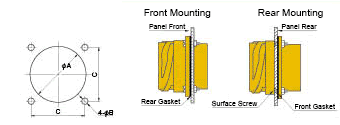
Panel Cut Size Drawing

| Compatible Shell Size |
φA ±0.5 |
φB +0.2 -0 |
C ±0.13 |
Mounting Screws (Reference) | Rear Mounting Panel Thickness Limit |
|
|---|---|---|---|---|---|---|
| Inch Screws | Metric Screws | |||||
| 18 | 30.2 | 3.3 | 26.97 | #4-40 | M3 | 3.0 or less |
| 20 | 34.9 | 3.3 | 29.36 | #4-40 | M3 | |
| 22 | 36.6 | 3.3 | 31.75 | #4-40 | M3 | |
| 24 | 39.7 | 4.3 | 34.92 | #6-32 | M4 | |
| 28 | 46.1 | 4.3 | 39.67 | #6-32 | M4 | |
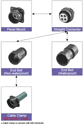
Combination Method

Combination Example

Konfigurieren
Basiseigenschaften
-
Compatible Shell Size
Filtern nach vsl. Lieferzeit
-
- Alle Produkte
- 5 Tage oder weniger
Optionale Eigenschaften
- Die Spezifikationen und Maße einiger Teile sind evtl. nicht vollständig enthalten. Genaue Details siehe Herstellerkataloge .


