C (D) G1-Z, Druckluftzylinder, doppeltwirkend, Standardkolbenstange (Teilenummern - CAD Download)
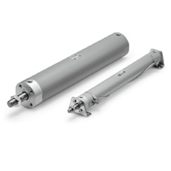
- Sonderpreis
(i)Hinweis
- See catalog for specification details.
- Product pictures are representations. CAD data is not supported for some model numbers.
Teilenummer
Hier finden Sie die Teilenummern
zu dem gesuchten Artikel
Air Cylinder, Standard Type, Double Acting, Single Rod CG1 Series Specifications
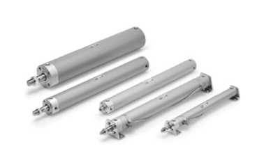
Air Cylinder, Standard Type, Double Acting, Single Rod CG1 Series external appearance
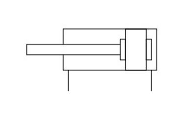
Symbol Rubber bumper
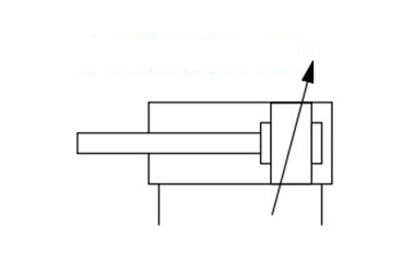
Symbol Air cushion
Specifications
| Bore Size (mm) | 20 | 25 | 32 | 40 | 50 | 63 | 80 | 100 | ||
|---|---|---|---|---|---|---|---|---|---|---|
| Action | Double acting, single rod | |||||||||
| Lubrication | Not required (non-lube) | |||||||||
| Applicable fluids | Air | |||||||||
| Proof pressure | 1.5 MPa | |||||||||
| Maximum operating pressure | 1.0 MPa | |||||||||
| Minimum operating pressure | 0.05 MPa | |||||||||
| Ambient and fluid temperature | Without auto switch: -10°C to 70°C (No freezing) With auto switch: -10°C to 60°C (No freezing) | |||||||||
| Piston speed | 50 to 1,000 mm/s | 50 to 700 mm/s | ||||||||
| Stroke length tolerance | Up to 1,000 (st 0 to +1.4) mm, up to 1,500 (st 0 to +1.8) mm | |||||||||
| Cushion | Rubber bumper, air cushion | |||||||||
| Mounting** | Basic, basic (without trunnion mounting female thread), axial foot, rod flange, head flange, rod trunnion type, head trunnion, clevis | |||||||||
| Allowable kinetic energy (J) | Rubber bumper | Rod end male thread | 0.28 | 0.41 | 0.66 | 1.20 | 2.00 | 3.40 | 5.90 | 9.90 |
| Rod end female thread | 0.11 | 0.18 | 0.29 | 0.52 | 0.91 | 1.54 | 2.71 | 4.54 | ||
| Air cushion | Rod end male thread | R: 0.35 H: 0.42 | R: 0.56 H: 0.65 | 0.91 | 1.80 | 3.40 | 4.90 | 11.80 | 16.70 | |
| Rod end female thread | 0.11 | 0.18 | 0.29 | 0.52 | 0.91 | 1.54 | 2.71 | 4.54 | ||
- *R: rod side, H: head side
- *Cylinder sizes ø80 (80‑mm diameter) and ø100 (100‑mm diameter) do not have basic (without trunnion mounting female thread), rod trunnion or head trunnion types. Foot, flange and clevis types of cylinder sizes ø20 to ø63 (20‑ to 63‑mm diameter) do not have trunnion mounting female thread. Operate the cylinder within the allowable kinetic energy.
Standard Strokes
(Unit: mm)
| Bore size | Standard strokeNote 1) | Maximum manufacturable strokeNote 2) |
|---|---|---|
| 20 | 25, 50, 75, 100, 125, 150, 200 | 201 to 1,500 |
| 25 | 25, 50, 75, 100, 125, 150, 200, 250, 300 | 301 to 1,500 |
| 32 | ||
| 40 | ||
| 50/63 | ||
| 80 | ||
| 100 |
Note 1) Intermediate strokes not listed above are produced to order.
Manufacture of intermediate strokes at 1 mm intervals is possible. (Spacers are not used.)
Note 2) The maximum manufacturable stroke shows the long stroke.
Note 3) Applicable strokes should be confirmed according to the usage. For details, refer to "Air Cylinders Model Selection" in the manufacturer's catalog.
In addition, products that exceed the standard stroke may not be able to fulfill the specifications due to deflection, etc.
Mounting Procedure
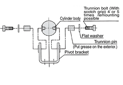
Mounting procedure for trunnion: ø20 to ø63 (20‑ to 63‑mm diameter)
Follow the procedures in the above figure when mounting a pivot bracket on the trunnion.
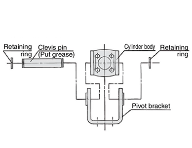
Mounting procedure for clevis: ø20 to ø63 (20‑ to 63‑mm diameter)
Follow the procedures in the above figure when mounting a pivot bracket on the clevis.
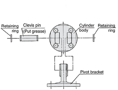
Mounting procedure for clevis: ø80 (80‑mm diameter), ø100 (100‑mm diameter)
Follow the procedures in the above figure when mounting a pivot bracket on the clevis.
Dimensional Outline Drawing (Dimensions Other Than Those Shown Below Are the Same As the Standard Type)
(Unit: mm)
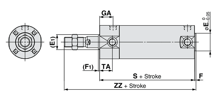
Rubber bumper dimensional outline drawing
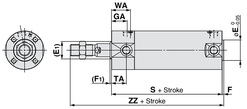
Air cushion dimensional outline drawing
| Bore size | (E1) | *E | (F1) | *F | GA | S | TA | WA | ZZ | |||
|---|---|---|---|---|---|---|---|---|---|---|---|---|
| Rc | NPT | G | Male thread | Female thread | ||||||||
| 32 | 17 | 18 | 2 | 2 | 18 | 16.5 | 77 (85) | 17 | 22 | 119 (127) | 93 (101) | |
| 40 | 21 | 25 | 2 | 2 | 19 | 19 | 84 (93) | 18 | 23 | 136 (145) | 101 (110) | |
| 50 | 26 | 30 | 2 | 2 | 21 | 21 | 97 (109) | 20 | 25 | 157 (169) | 115 (127) | |
| 63 | 26 | 32 | 2 | 2 | 21 | 21 | 97 (109) | 20 | 25 | 157 (169) | 115 (127) | |
| 80 | 32 | 40 | 3 | 3 | 28 | 25.5 | 116 (130) | - | 32 | 190 (204) | 138 (152) | |
| 100 | 37 | 50 | 3 | 3 | 29 | 26.5 | 117 (131) | - | 33 | 119 (205) | 142 (156) | |
- *Dimensions marked with * are the same as the standard type.
- *Dimensions inside () are for long stroke.
Structural drawing
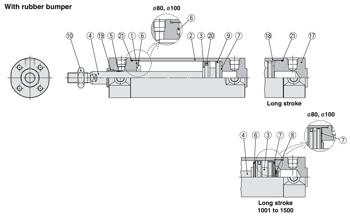
Rubber bumper structural drawing

Rubber bumper structural drawing
Component Parts
| Number | Description | Material | Note | |
|---|---|---|---|---|
| 1 | Rod cover | Aluminum alloy | Hard anodized | |
| 2 | Tube cover | Aluminum alloy | Hard anodized | |
| 3 | Piston | Aluminum alloy | - | |
| 4 | Piston rod | Stainless steel | For ø20 (20‑mm diameter), ø25 (25‑mm diameter) with built-in magnet | |
| Carbon steel* | Hard chrome plating* | |||
| 5 | Bushing | Resin/Copper alloy (Multiple layers) | - | |
| 6 | Bumper | Resin | ø32 (32‑mm diameter) or larger is common | |
| 7 | Bumper | Resin | ||
| 8 | Retaining Ring | Stainless steel | Not available for ø80 (80‑mm diameter), ø100 (100‑mm diameter) | |
| 9 | Wear ring | Resin | - | |
| 10 | Rod-end nut | Carbon steel | Zinc chromated | |
| 11 | Cushion ring A | Aluminum alloy | - | |
| 12 | Cushion ring B | Aluminum alloy | - | |
| 13 | Seal retainer | Rolled steel | Zinc chromated | |
| 14 | Cushion valve | ø40 (40‑mm diameter) or smaller | Carbon steel | Electroless nickel plating |
| ø50 (diameter 50 mm) or more | Steel wire | Zinc chromated | ||
| 15 | Cushion seal A | Urethane | ø32 (32‑mm diameter) or larger is common | |
| 16 | Cushion seal B | Urethane | ||
| 17 | Head cover | Aluminum alloy | Hard anodized | |
| 18 | Cylinder tube | Aluminum alloy | Hard anodized | |
| 19 | Rod seal | NBR | - | |
| 20 | Piston seal | NBR | - | |
| 21 | Tube gasket | NBR | - | |
| 22 | Valve seal | NBR | - | |
Note) For cylinders with auto switches, the magnet is installed in the piston.
*The material for ø20 (20‑mm diameter) and ø25 (25‑mm diameter) cylinders with auto switches is stainless steel.
*See the manufacturer's catalog for product information other than the above.
Teilenummer
|
|---|
| CDG1BA32-1350Z |
| CDG1BA50-1350Z |
| CDG1BA50TF-1350Z |
| CDG1BN100-1350Z |
| CDG1LN80-1350Z |
| Teilenummer |
Standard-Stückpreis
| Mindestbestellmenge | Mengenrabatt | Zylinder-Innen-Ø: D (Ø) | Hub: L (mm) | Umgebung, Anwendungen | Cushion | Specifications | Port thread type | Auto Switch | Lead Wire Length (m) | Number of Switches | Swinging Receiving Metal | Rod Tip Metal Fitting | Type of Mount Support | Rod Tip Shape | Bellows | Custom-made Specifications | |
|---|---|---|---|---|---|---|---|---|---|---|---|---|---|---|---|---|---|---|---|
165.73 € | 1 | 7 Arbeitstage | 32 | 1,350 | Standard | Pneumatische Dämpfung | Eingebauter Magnet | Rc | Ohne Signalgeber | - | - | Ohne Befestigungselement | Ohne Befestigungselement | Grundausführung | Stabende Außengewinde | Ohne Faltenbalg | Ohne | ||
355.74 € | 1 | 7 Arbeitstage | 50 | 1,350 | Standard | Pneumatische Dämpfung | Eingebauter Magnet | Rc | Ohne Signalgeber | - | - | Ohne Befestigungselement | Ohne Befestigungselement | Grundausführung | Stabende Außengewinde | Ohne Faltenbalg | Ohne | ||
355.74 € | 1 | 7 Arbeitstage | 50 | 1,350 | Standard | Pneumatische Dämpfung | Eingebauter Magnet | G | Ohne Signalgeber | - | - | Ohne Befestigungselement | Ohne Befestigungselement | Grundausführung | Stabende Außengewinde | Ohne Faltenbalg | Ohne | ||
561.23 € | 1 | 7 Arbeitstage | 100 | 1,350 | Standard | Kautschukdämpfer | Eingebauter Magnet | Rc | Ohne Schalter | - | - | Ohne Befestigungselement | Ohne Befestigungselement | Grundausführung | Stabende Außengewinde | Ohne Faltenbalg | Ohne | ||
431.11 € | 1 | 7 Arbeitstage | 80 | 1,350 | Standard | Kautschukdämpfer | Eingebauter Magnet | Rc | Ohne Schalter | - | - | Ohne Befestigungselement | Ohne Befestigungselement | Axialer Fußmodell | Stabende Außengewinde | Ohne Faltenbalg | Ohne |
Loading...
Grundlegende Informationen
| Zylinder, Betriebsmethode | Double-Acting | Stange, Betriebsmethode | Einfach-Stangen | Grundkörper, Form | Standard |
|---|---|---|---|---|---|
| Zusätzliche Funktionen | Standard | Operating Pressure(MPa) | 0,05 bis 1,0 |
Konfigurieren
Basiseigenschaften
-
Zylinder-Innen-Ø: D(Ø)
-
Umgebung, Anwendungen
- Standard
- Niedrige Drehzahl
- Wärmebeständigkeit
-
Cushion
- Kautschukdämpfer
- Pneumatische Dämpfung
-
Specifications
- Eingebauter Magnet
- Ohne Magnet
-
Port thread type
- M5 × 0,8
- G
- NPT
- Rc
-
Auto Switch
-
Lead Wire Length(m)
- 0,5 (M12 4-Pin A-cord [Normal-key] Steckverbinder)
- 0.5
- 1
- 3
- 5
- Ohne
-
Number of Switches
- 1
- 2
- 3
-
Swinging Receiving Metal
- Auslieferung mit Schwenkbefestigung
- Ohne Befestigungselement
-
Rod Tip Metal Fitting
- Einfacher Gelenkbolzen
- Ohne Befestigungselement
- U-Gelenkbolzen
-
Type of Mount Support
- Axialer Fußmodell
- Basic (ohne weiblich (female))
- Flanschart
- Flanschbefestigung Kopfseite
- Gabelform
- Grundausführung
- Kopfzapfen
- Stab Zapfenmodell
-
Rod Tip Shape
- Stabende Außengewinde
- Stabende Innengewinde
-
Bellows
- Hitzebeständige Plane
- Nylon
- Ohne Faltenbalg
-
Custom-made Specifications
- Kältebeständiger Zylinder (-40 bis 70 °C)
- Hitzebeständiger Zylinder (-10 bis 150 °C)
- Niedrige Drehzahl Zylinder (5 bis 50 mm/s)
- Niedrige Drehzahl Zylinder (10 bis 50 mm/s)
- Axialer Anschluss an Abdeckung
- Fluororber-Dichtung
- Größere Rohranschluss Durchmesser
- Material: Rostfreier Stahl
- Materialien: Rostfreier Stahl, Fluorgummidichtung
- Mit Spulenschaber
- Mit leistungsstarkem Schaber
- Mit leistungsstarkem Schaber + Material: Rostfreier Stahl
- Ohne
- Schienenmontage für automatische Schalterschiene (Modell A)
- Schienenmontage für automatische Schalterschiene (Modell B)
- Zylinder
- Zylinder mit eingebautem Stoßdämpfer an der Kopfdeckelseite
-
Ausführung
- CDG1
- CG1
-
Hub: L(mm)
- 1
- 1,000
- 1,010
- 1,020
- 1,050
- 1,075
- 1,100
- 1,110
- 1,111
- 1,150
- 1,160
- 1,170
- 1,200
- 1,250
- 1,260
- 1,300
- 1,320
- 1,340
- 1,350
- 1,400
- 1,410
- 1,450
- 1,500
- 5
- 6
- 10
- 12
- 13
- 14
- 15
- 16
- 17
- 18
- 19
- 20
- 21
- 22
- 25
- 26
- 27
- 28
- 29
- 30
- 32
- 33
- 35
- 36
- 37
- 38
- 40
- 41
- 45
- 50
- 52
- 53
- 54
- 55
- 56
- 57
- 58
- 60
- 62
- 63
- 65
- 66
- 67
- 68
- 70
- 72
- 75
- 76
- 77
- 79
- 80
- 81
- 82
- 85
- 90
- 95
- 100
- 103
- 105
- 109
- 110
- 115
- 116
- 117
- 118
- 120
- 122
- 125
- 126
- 127
- 130
- 134
- 135
- 137
- 138
- 139
- 140
- 145
- 150
- 152
- 153
- 155
- 156
- 160
- 165
- 170
- 175
- 180
- 185
- 187
- 190
- 192
- 193
- 195
- 200
- 205
- 210
- 215
- 220
- 225
- 228
- 230
- 235
- 240
- 245
- 250
- 251
- 254
- 255
- 260
- 265
- 270
- 275
- 276
- 280
- 283
- 285
- 290
- 295
- 300
- 305
- 310
- 312
- 315
- 320
- 325
- 330
- 335
- 340
- 345
- 350
- 352
- 355
- 359
- 360
- 365
- 370
- 375
- 380
- 385
- 390
- 395
- 400
- 405
- 410
- 415
- 419
- 420
- 425
- 430
- 435
- 440
- 450
- 455
- 460
- 465
- 470
- 475
- 480
- 485
- 490
- 495
- 500
- 505
- 510
- 515
- 520
- 525
- 530
- 535
- 540
- 550
- 555
- 560
- 565
- 570
- 575
- 580
- 585
- 590
- 595
- 600
- 610
- 615
- 620
- 625
- 630
- 635
- 640
- 645
- 650
- 653
- 660
- 665
- 670
- 675
- 680
- 690
- 700
- 710
- 715
- 720
- 730
- 735
- 740
- 745
- 750
- 755
- 760
- 770
- 780
- 785
- 790
- 800
- 810
- 815
- 820
- 825
- 830
- 850
- 860
- 870
- 880
- 900
- 910
- 920
- 930
- 940
- 950
- 975
- 980
-
Filtern nach CAD Format
- 2D
- 3D
Filtern nach vsl. Lieferzeit
-
- Alle Produkte
- Versand am selben Tag
- 4 Tage oder weniger
- 7 Tage oder weniger
- 9 Tage oder weniger
- 26 Tage oder weniger
- 36 Tage oder weniger
- 45 Tage oder weniger
- 46 Tage oder weniger
- 48 Tage oder weniger
- 49 Tage oder weniger
Optionale Eigenschaften
- Die Spezifikationen und Maße einiger Teile sind evtl. nicht vollständig enthalten. Genaue Details siehe Herstellerkataloge .


