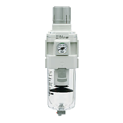
Druckregeler mit Filter / Filterdruckregler AW20 bis 60-B, Filterdruckregler mit Rücklauffunktion AW20K bis 60K-B (AW40-N04DH-8Z-B)
- Sonderpreis
Produktdetails:
Hersteller-Teilenummer: AW40-N04DH-8Z-B
Marke: SMC
Preis: 120.11 €
Lieferzeit: 26 Arbeitstage
Technische Daten:
Anschluss-Ø: NPT1/2
Max. Betriebsdruck: 1 MPa
Werkstoffe des Gehäuses: [Kunststoff] 00018
Schalenschutz: Verfügbar
Auslassmechanismus: Entlastungsart
(i)Hinweis
- Die im Bild gezeigten Produkte sind repräsentativ. CAD-Daten werden für einige Modellnummern nicht unterstützt.
Teilenummer
Hier finden Sie die Teilenummern
zu dem gesuchten Artikel
AW40-N04DH-8Z-B
Filter Regulator AW20-B To AW60-B And Filter Regulator With Backflow Function AW20K-B To AW60K-B Details
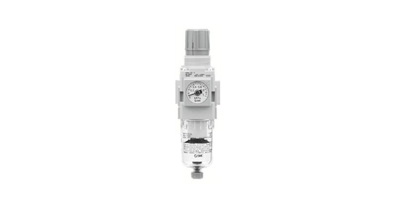
AW20-B/AW20K-B: product images
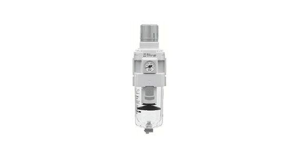
AW40-B/AW40K-B: product images
Filter Regulator AW20-B To AW60-B And Filter Regulator With Backflow Function AW20K-B To AW60K-B Specifications
| Model | AW20-B | AW30-B | AW40-B | AW40-06-B | AW60-B |
|---|---|---|---|---|---|
| Port size | 1/8, 1/4 | 1/4, 3/8 | 1/4, 3/8, 1/2 | 3/4 | 3/4, 1 |
| Pressure gauge port size Note 1) | 1/8 | ||||
| Applicable fluids | Air | ||||
| Ambient and fluid temperature Note 2) | -5 to 60°C (no freezing) | ||||
| Proof pressure | 1.5 MPa | ||||
| Maximum operating pressure | 1.0 MPa | ||||
| Set pressure range | 0.05 to 0.85 MPa | ||||
| Nominal filtration rating | 5 mm | ||||
| Drain capacity (cm3) | 8 | 25 | 45 | ||
| Bowl materials | Polycarbonate | ||||
| Bowl guard | Semi-standard (steel) | Standard equipment (polycarbonate) | |||
| Construction | Relieving type | ||||
| Weight (kg) | 0.20 | 0.36 | 0.66 | 0.72 | 2.05 |
Note 1) For the specification with the square embedded type pressure gauge and the specification with the digital pressure switch, there are no pressure gauge connection screws.
Note 2) With a digital pressure switch: −5 to 50°C.
Options / Part No.
| Optional specification | Model | ||||||
|---|---|---|---|---|---|---|---|
| AW20(K)-B | AW30(K)-B | AW40(K)-B | AW40(K)-06-B | AW60(K)-B | |||
| Bracket assembly Note 1) | AW23P-270AS | AR33P-270AS | AR43P-270AS | AW62P-270AS | |||
| Set nut | AR23P-260S | AR33P-260S | AR43P-260S | -Note 2) | |||
| Pressure gauge | Round-type Note 3) | Standard | G36-10-□01 | G46-10-□01 | |||
| 0.02 to 0.2‑MPa setting | G36-4-□01 | G46-4-□01 | |||||
| Round-type Note 3) (with color zone) | Standard | G36-10-□01-L | G46-10-□01-L | ||||
| 0.02 to 0.2‑MPa setting | G36-4-□01-L | G46-4-□01-L | |||||
| Square Note 4) embedded type | Standard | GC3-10AS [GC3P-010AS (pressure gauge cover only)] | |||||
| 0.02 to 0.2‑MPa setting | GC3-4AS [GC3P-010AS (pressure gauge cover only)] | ||||||
| Digital pressure switch Note 5) | NPN output / Wiring bottom entry | ISE35-N-25-MLA [ISE35-N-25-M (main switch unit only)] | |||||
| NPN output / Wiring top entry | ISE35-R-25-MLA [ISE35-R-25-M (main switch unit only)] | ||||||
| PNP output / Wiring bottom entry | ISE35-N-65-MLA [ISE35-N-65-M (main switch unit only)] | ||||||
| PNP output / Wiring top entry | ISE35-R-65-MLA [ISE35-R-65-M (main switch unit only)] | ||||||
Note 1) Assembly of a bracket and set nuts.
The AW60(K)-B has mounting screws (2 pcs.) included.
Note 2) Consult separately with the manufacturer regarding the set nuts for the AW60(K)-B.
Note 3) The □ in the part numbers for round-type pressure gauges indicates the connection thread type.
Insert no symbol for Rc, and use "N" for NPT.
Contact the manufacturer regarding the supply of psi unit specification pressure gauges.
Note 4) Including O-ring (1 pc.) and mounting screws (2 pcs.).
[ ]: Pressure gauge cover only.
Note 5) In addition to the pressure switch, it also includes a lead wire with connector (2 m), adapter, lock pin, O-ring (1 pc.) and mounting screws (2 pcs.).
[ ]: Switch unit only.
If mounting a pressure switch to the AW60(K)-B, a separate special mounting adapter (pressure switch adapter assembly: AW63P-310AS),
and special mounting screws (M3 × 0.5 × 14) (delivered together with the mounting adapter) are required.
Bowl assembly / Part number
| Bowl materials | Drain discharge mechanism | Drain port | Other | Model | ||||
|---|---|---|---|---|---|---|---|---|
| AW20-B | AW30-B | AW40-B | AW40-06-B | AW60-B | ||||
| Polycarbo -nate | Manual discharge | With drain cock | - | C2SF-A | - | - | ||
| With bowl guard | C2SF-C-A | C3SF-A | C4SF-A | |||||
| Drain cock, with barb fitting | With bowl guard | - | C3SF-W-A | C4SF-W-A | ||||
| With drain guide (without valve function) | - | C2SF□-J-A | - | - | ||||
| With bowl guard | C2SF□-CJ-A | C3SF□-J-A | C4SF□-J-A | |||||
| Automatic discharge Note) (auto drain) | Normally closed (N.C.) | - | AD27-A | - | - | |||
| With bowl guard | AD27-C-A | AD37□-A | AD47□-A | |||||
| Normally open (N.O.) | With bowl guard | - | AD38□-A | AD48□-A | ||||
| Nylon | Manual discharge | With drain cock | - | C2SF-6-A | - | - | ||
| With bowl guard | C2SF-6C-A | C3SF-6-A | C4SF-6-A | |||||
| Drain cock, with barb fitting | With bowl guard | - | C3SF-6W-A | C4SF-6W-A | ||||
| With drain guide (without valve function) | - | C2SF□-6J-A | - | - | ||||
| With bowl guard | C2SF□-6CJ-A | C3SF□-6J-A | C4SF□-6J-A | |||||
| Automatic discharge Note) (auto drain) | Normally closed (N.C.) | - | AD27-6-A | - | - | |||
| With bowl guard | AD27-6C-A | AD37□-6-A | AD47□-6-A | |||||
| Normally open (N.O.) | With bowl guard | - | AD38□-6-A | AD48□-6-A | ||||
| Metal | Manual discharge | With drain cock | - | C2SF-2-A | C3SF-2-A | C4SF-2-A | ||
| With level gauge | - | C3LF-8-A | C4LF-8-A | |||||
| With drain guide (without valve function) | - | C2SF□-2J-A | C3SF□-2J-A | C4SF□-2J-A | ||||
| With level gauge | - | C3LF□-8J-A | C4LF□-8J-A | |||||
| Automatic discharge Note) (auto drain) | Normally closed (N.C.) | - | AD27-2-A | AD37□-2-A | AD47□-2-A | |||
| With level gauge | - | AD37□-8-A | AD47□-8-A | |||||
| Normally open (N.O.) | - | - | AD38□-2-A | AD48□-2-A | ||||
| With level gauge | - | AD38□-8-A | AD48□-8-A | |||||
Note) Minimum operating pressure - N.O. Type: 0.1 MPa (AD38-A, AD48-A); N.C. Type: 0.1 MPa (AD27-A), and 0.15 MPa (AD37-A, AD47-A).
The bowl assembly comes with a bowl seal. The □ in the bowl assembly part number indicates a tubing thread type (applicable tubing for an auto drain).
No indication is necessary for Rc thread; however, indicate N for NPT thread, and F for G thread. (For auto drain, Nil: ø10 [diameter 10 mm]; N: ø3/8 [diameter 3/8]")
Please consult with manufacturer separately regarding psi and °F unit display specifications.
Model Number Notation

Model number example
| - | Code | Contents | (1) | ||||||
|---|---|---|---|---|---|---|---|---|---|
| Body size | |||||||||
| 20 | 30 | 40 | 60 | ||||||
| (2) | With backflow function | No symbol | Without backflow function | ● | ● | ● | ● | ||
| K Note 1) | With backflow function | ● | ● | ● | ● | ||||
| (3) | Pipe thread type | No symbol | Rc | ● | ● | ● | ● | ||
| N Note 2) | NPT | ● | ● | ● | ● | ||||
| F Note 3) | G | ● | ● | ● | ● | ||||
| (4) | Port size | 01 | 1/8 | ● | - | - | - | ||
| 02 | 1/4 | ● | ● | ● | - | ||||
| 03 | 3/8 | - | ● | ● | - | ||||
| 04 | 1/2 | - | - | ● | - | ||||
| 06 | 3/4 | - | - | ● | ● | ||||
| 10 | 1 | - | - | - | ● | ||||
| (5) | Note 4) Option | a | Mounting | No symbol | Without optional mounting parts | ● | ● | ● | ● |
| B Note 5) | With Bracket | ● | ● | ● | ● | ||||
| H | With set nut (for panel mount) | ● | ● | ● | - | ||||
| b | Float type auto drain | No symbol | Without auto drain | ● | ● | ● | ● | ||
| C Note 6) | N.C. (Normally Closed) Drain port is closed when no pressure is applied | ● | ● | ● | ● | ||||
| D Note 7) | N.O. (Normally Open) Drain port is open when no pressure is applied | - | ● | ● | ● | ||||
| c | Pressure gauge Note 8) | No symbol | Without pressure gauge | ● | ● | ● | ● | ||
| E | Square embedded-type pressure gauge (with limit indicator) | ● | ● | ● | ● | ||||
| G | Round-type pressure gauge (with limit indicator) | ● | ● | ● | ● | ||||
| M | Round-type pressure gauge (with color zone) | ● | ● | ● | ● | ||||
| Digital Note 9) Pressure switch | E1 | Output: NPN output / Lead wire electrical entry: wiring bottom entry | ● | ● | ● | ● | |||
| E2 | Output: NPN output / Lead wire electrical entry: wiring top entry | ● | ● | ● | ● | ||||
| E3 | Output: PNP output / Lead wire electrical entry: wiring bottom entry | ● | ● | ● | ● | ||||
| E4 | Output: PNP output / Lead wire electrical entry: wiring top entry | ● | ● | ● | ● | ||||
| (6) | Semi-standard | d | Set pressure Note 10) | No symbol | 0.05 to 0.85‑MPa setting | ● | ● | ● | ● |
| 1 | 0.02 to 0.2‑MPa setting | ● | ● | ● | ● | ||||
| e | Bowl | No symbol | Polycarbonate bowl | ● | ● | ● | ● | ||
| 2 | Metal bowl | ● | ● | ● | ● | ||||
| 6 | Nylon bowl | ● | ● | ● | ● | ||||
| 8 | Metal bowl with level gauge | - | ● | ● | ● | ||||
| C | With bowl guard | ● | -Note 12) | -Note 12) | -Note 12) | ||||
| 6C | With bowl guard (nylon bowl) | ● | -Note 13) | -Note 13) | -Note 13) | ||||
| f | Drain port Note 14) | No symbol | With drain cock | ● | ● | ● | ● | ||
| J Note 15) | Drain guide 1/8 | ● | - | - | - | ||||
| Drain guide 1/4 | - | ● | ● | ● | |||||
| W Note 16) | Drain cock with barb fitting | - | ● | ● | ● | ||||
| - | Code | Contents | (1) | ||||||
|---|---|---|---|---|---|---|---|---|---|
| Body size | |||||||||
| 20 | 30 | 40 | 60 | ||||||
| (6) | Semi-standard | g | Exhaust mechanism | No symbol | Relieving type | ● | ● | ● | ● |
| N | Non-relieving type | ● | ● | ● | ● | ||||
| h | Flow direction | No symbol | Flow direction: left → right | ● | ● | ● | ● | ||
| R | Flow direction: right → left | ● | ● | ● | ● | ||||
| i | Pressure unit | No symbol | Name plate, bowl caution plate and pressure gauge units: MPa | ● | ● | ● | ● | ||
| Z Note 17) | Name plate, bowl caution plate and pressure gauge units: psi, °F | ○ Note 19) | ○ Note 19) | ○ Note 19) | ○ Note 19) | ||||
| ZA Note 18) | Digital pressure switch: with unit selection function | △ Note 20) | △ Note 20) | △ Note 20) | △ Note 20) | ||||
Note 1) Set the inlet pressure to at least 0.05‑MPa higher than the set pressure.
Note 2) Drain guide is NPT1/8 (applicable to the AW20(K)-B); and NPT1/4 (applicable to the AW30(K)-B to AW60(K)-B). The auto drain port comes with ø3/8" one-touch fitting (applicable to the AW30(K)-B to AW60(K)-B).
Note 3) Drain guide is G1/8 (applicable to the AW20(K)-B); and G1/4 (applicable to the AW30(K)-B to AW60(K)-B).
Note 4) Options B, G, H, M are not assembled and are supplied loose at the time of shipment.
Note 5) Set nuts are included with the bracket. (Applicable to the AW20(K)-B to AW40(K)-B). The AW60(K)-B has mounting screws (2 pcs.) included.
Note 6) When pressure is not applied, condensate which does not start the auto drain mechanism will remain in the drain bowl. Therefore manual release before ending operations is recommended.
Note 7) If the compressor used is small (0.75 kW, discharge flow rate is less than 100 L/min [ANR]), air leakage from the drain cock may occur when operations start. As such an N.C. type is recommended.
Note 8) When the pressure gauge is attached, a 1.0‑MPa specification will be fitted for standard (0.85‑MPa setting) type; 0.4 MPa for the 0.2‑MPa type.
Note 9) When choosing with H (panel mount), the installation space for lead wires will not be secured. In this case, select "wiring top entry" for the electrical entry.
Note 10) Pressure can be set higher than the specification pressure in some cases, but use with the pressure within the specified range.
Note 11) For chemical resistance of the bowl, refer to the table below "Effects of atmosphere of organic solvents and chemicals and where these elements are likely to adhere to the equipment. Chemical data for substances causing degradation (Reference)."
Note 12) A bowl guard is provided as standard (polycarbonate).
Note 13) A bowl guard is provided as standard (nylon).
Note 14) Float type auto drain: Cannot be selected in combination with C, D.
Note 15) Does not include a valve function.
Note 16) Metal bowl: Cannot be selected in combination with 2, 8.
Note 17) Thread type: NPT is applicable. Under new Japanese measurement laws, this product is only available for sale outside of Japan (SI units are used in Japan). Round-type pressure gauge (with color zone): cannot be used in combination with M. Available on request as separate, special order. The digital pressure switch, which has the unit selection function, has an default setting of psi.
Note 18) Options: E1, E2, E3, E4. Under new Japanese measurement laws, this product is only available for sale outside of Japan (SI units are used in Japan).
Note 19) ○ is for thread type NPT only.
Note 20) △: Combination available for options E1, E2, E3, E4.
Effects of atmosphere of organic solvents and chemicals and where these elements are likely to adhere to the equipment. Chemical data for substances causing degradation (Reference)
| Type | Chemical name | Application examples | Materials | |
|---|---|---|---|---|
| Polycarbonate | Nylon | |||
| Acid | Hydrochloric acid Sulfuric acid, Phosphoric acid Chromic acid | Acid washing liquid for metals | Possible use | × |
| Alkaline | Sodium hydroxide (caustic soda) Potassium hydroxide Calcium hydroxide Ammonia water Sodium carbonate | Degreasing of metals Industrial salts Water-soluble cutting oil | × | ○ |
| Inorganic salts | Sodium sulfide Potassium nitrate Sodium sulfate | - | × | Possible use |
| Chlorinated solvents | Carbon tetrachloride Chloroform Ethylene chloride Methylene chloride | Cleansing liquid for metals Printing ink Dilution | × | Possible use |
| Aromatic series | Benzene Toluene Paint thinner | Coatings Dry cleaning | × | Possible use |
| Ketone | Acetone Methyl ethyl ketone Cyclohexane | Photographic film Dry cleaning Textile industries | × | × |
| Alcohol | Ethyl alcohol IPA Methyl alcohol | Antifreeze Adhesive | Possible use | × |
| Oil | Gasoline Kerosene | - | × | ○ |
| Ester | Phthalic acid dimethyl Phthalic acid diethyl Acetic acid | Synthetic oil Anti-rust additives | × | ○ |
| Ether | Methyl ether Ethyl ether | Brake oil additives | × | ○ |
| Amino | Methyl amino | Cutting oil Brake oil additives Rubber accelerator | × | × |
| Other | Thread-lock fluid Seawater Leak tester | - | × | Possible use |
○: Essentially safe △: Some effects may occur ×: Effects will occur
- *When the above factors are present, or if there is some doubt, use a metal bowl for safety.
Structural Drawings

AW20(K)-B: structural drawings

AW30(K)-B/AW40(K)-B: structural drawings

AW60(K)-B: structural drawings

AW20K-B to AW60K-B (Filter Regulator With Backflow Function): structural drawings
Component Parts
| Number | Part name | Materials | Model | Color |
|---|---|---|---|---|
| 1 | Body | Aluminum die-cast | AW20-B AW60-B | White |
| 2 | Bonnet | Polyacetal | AW20-B to AW40-B | White |
| Aluminum die-cast | AW60-B | White | ||
| 3 | Housing | Aluminum die-cast | AW60-B | White |
Replacement Parts
| Number | Part name | Materials | Part number | ||||
|---|---|---|---|---|---|---|---|
| AW20(K)-B | AW30(K)-B | AW40(K)-B | AW40(K)-06-B | AW60(K)-B | |||
| 4 | Valve assembly | Brass, HNBR | AW20P-340AS | AW30P-340AS | AW40P-340AS | AW60P-090AS | |
| 5 | Filter element | Non‐woven fabric | AF20P-060S | AF30P-060S | AF40P-060S | AW60P-060S | |
| 6 | Diaphragm assembly | Weatherable NBR | AR20P-150AS | AR30P-150AS | AR40P-150AS | AR50P-150AS | |
| 7 | Bowl seal | NBR | C2SFP-260S | C32FP-260S | C42FP-260S | ||
| 8 | Bowl assembly Note 1) | Polycarbonate | C2SF-A | C3SF-ANote 2) | C4SF-ANote 2) | ||
| 9 | Check valve assembly Note 3) | - | AR23KP-020AS | ||||
Note 1) The bowl assembly includes a bowl O-ring. Contact the manufacturer separately for psi, °F unit display specifications.
Note 2) Bowl assembly for the AW30(K)-B to AW60(K)-B models comes with a bowl guard (made of polycarbonate).
Note 3) Check valve assembly is applicable only for specifications with the backflow function (AW20(K)-B to AW60(K)-B). Assembly consisting of a check valve cover, check valve body and mounting screws (2 pcs.).
Filter Regulator AW20-B To AW60-B And Filter Regulator With Backflow Function AW20K-B To AW60K-B Dimensions
AW20(K)-B
(Unit: mm)
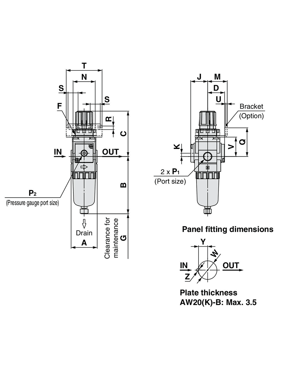
AW20(K)-B: dimensional drawings
AW30(K)-B to AW40(K)-06-B
(Unit: mm)
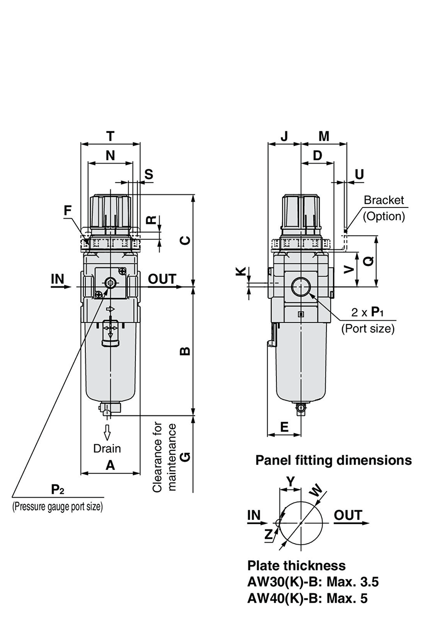
AW30(K)-B to AW40(K)-06-B: dimensional drawing
AW60(K)-B
(Unit: mm)
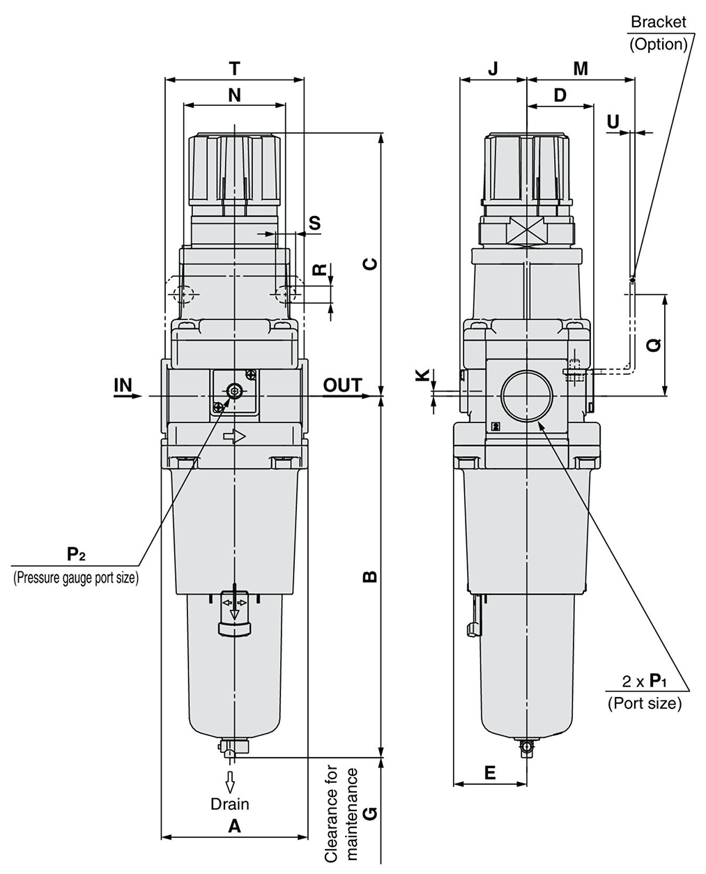
AW60(K)-B: dimensional drawing
(Unit: mm)
| Option | Square embedded type pressure gauge | Digital pressure switch | Round-type pressure gauge | Round-type pressure gauge (with color zone) |
|---|
| Compatible models | AW20(K)-B | AW20(K)-B | AW30(K)-B to AW60(K)-B | ||
|---|---|---|---|---|---|
| Option / Semi-standard specifications | With auto-drain (N.C.) | Metal bowl | With drain guide | Metal bowl with drain guide | With auto-drain (N.O./N.C.) |
| Compatible models | AW30(K)-B to AW60(K)-B | |||||
|---|---|---|---|---|---|---|
| Option / Semi-standard specifications | Metal bowl | Metal bowl with drain guide | Metal bowl with level gauge | Metal bowl with drain guide with level gauge | With drain guide | Drain cock with barb fitting |
(Unit: mm)
| Model | Standard specification | ||||||||||
|---|---|---|---|---|---|---|---|---|---|---|---|
| P 1 | P 2 | A | B | C Note) | D | E | F | G | J | K | |
| AW20(K)-B | 1/8, 1/4 | 1/8 | 40 | 87.6 | 72.4 | 26 | - | M28 × 1 | 40 | 26 | 5 |
| AW30(K)-B | 1/4, 3/8 | 1/8 | 53 | 115.1 | 85.6 | 29.4 | 30 | M38 × 1.5 | 55 | 29.4 | 3.5 |
| AW40(K)-B | 1/4, 3/8, 1/2 | 1/8 | 70 | 147.1 | 91.7 | 37.3 | 38.4 | M42 × 1.5 | 80 | 37.3 | 1.5 |
| AW40(K)-06-B | 3/4 | 1/8 | 75 | 149.1 | 93.2 | 37.3 | 38.4 | M42 × 1.5 | 80 | 37.3 | 1.2 |
| AW60(K)-B | 3/4, 1 | 1/8 | 95 | 234.1 | 175.5 | 43.3 | 47.5 | - | 30 | 43.3 | 3.2 |
| Model | Option specification | |||||||
|---|---|---|---|---|---|---|---|---|
| Square type pressure gauge | Digital pressure switch | Round-type pressure gauge | Round-type pressure gauge (with color zone) | |||||
| H | J | H | J | H | J | H | J | |
| AW20(K)-B | □28 | 27 | □27.8 | 37.5 | ø37.5 (diameter 37.5 mm) | 62.5 | ø37.5 (diameter 37.5 mm) | 63.5 |
| AW30(K)-B | □28 | 30.4 | □27.8 | 40.9 | ø37.5 (diameter 37.5 mm) | 65.9 | ø37.5 (diameter 37.5 mm) | 66.9 |
| AW40(K)-B | □28 | 38.3 | □27.8 | 48.8 | ø42.5 (diameter 42.5 mm) | 74.8 | ø42.5 (diameter 42.5 mm) | 74.8 |
| AW40(K)-06-B | □28 | 38.3 | □27.8 | 48.8 | ø42.5 (diameter 42.5 mm) | 74.8 | ø42.5 (diameter 42.5 mm) | 74.8 |
| AW60(K)-B | □28 | 44.3 | □27.8 | 61.3 | ø42.5 (diameter 42.5 mm) | 80.8 | ø42.5 (diameter 42.5 mm) | 80.8 |
| Model | Option specification | |||||||||||
|---|---|---|---|---|---|---|---|---|---|---|---|---|
| Bracket mounting dimensions | Panel mount | With auto drain | ||||||||||
| M | N | Q | R | S | T | U | V | W | Y | Z | B | |
| AW20(K)-B | 30 | 34 | 43.9 | 5.4 | 15.4 | 55 | 2.3 | 29.7 | 28.5 | 14 | 6 | 104.9 |
| AW30(K)-B | 41 | 40 | 45.8 | 6.5 | 8 | 53 | 2.3 | 31.1 | 38.5 | 19 | 7 | 156.8 |
| AW40(K)-B | 50 | 54 | 54 | 8.5 | 10.5 | 70 | 2.3 | 35.5 | 42.5 | 21 | 7 | 186.9 |
| AW40(K)-06-B | 50 | 54 | 55.5 | 8.5 | 10.5 | 70 | 2.3 | 37 | 42.5 | 21 | 7 | 188.9 |
| AW60(K)-B | 70 | 66 | 65.8 | 11 | 13 | 90 | 3.2 | - | - | - | - | 273.9 |
| Model | Semi-standard specifications | |||||
|---|---|---|---|---|---|---|
| With barb fittings | With drain guide | Metal bowl | Metal bowl with drain guide | Metal bowl with level gauge | Metal bowl with level gauge with drain guide | |
| B | B | B | B | B | B | |
| AW20(K)-B | - | 91.4 | 87.4 | 93.9 | - | - |
| AW30(K)-B | 123.6 | 121.9 | 117.6 | 122.1 | 137.6 | 142.1 |
| AW40(K)-B | 155.6 | 153.9 | 149.6 | 154.1 | 169.6 | 174.1 |
| AW40(K)-06-B | 157.6 | 155.9 | 151.6 | 156.1 | 171.6 | 176.1 |
| AW60(K)-B | 240.9 | 242.6 | 236.6 | 241.1 | 256.6 | 261.1 |
Note) The dimension C is the length when the filter regulator knob (handle) is unlocked.
Teilenummer
|
|---|
| AW40-N04DH-8Z-B |
| Teilenummer |
Standard-Stückpreis
| Mindestbestellmenge | Mengenrabatt | Anschluss-Ø | Max. Betriebsdruck (MPa) | Werkstoffe des Gehäuses | Schalenschutz | Auslassmechanismus | Durchflussrichtung | Ablasshahn | Manometer | Size of Body | Set Pressure | Drain Outlet | Pressure Unit | Maßgeschneiderte Spezifikationen | Filterregler Rückflussfunktion | Zubehör | |
|---|---|---|---|---|---|---|---|---|---|---|---|---|---|---|---|---|---|---|---|
120.11 € | 1 | 26 Arbeitstage | NPT1/2 | 1 | [Kunststoff] 00018 | Verfügbar | Entlastungsart | [Standarddurchfluss (von links nach rechts)] Durchflussrichtung | [Automatisch/manuell] N.O. (Schließer, Grundstellung offen) bei drucklosem Zustand mit Abwasseremissionen | Nein (ohne Druckanschlussstecker) | 40 | 0,05 bis 0,85 MPa | Mit Ablasshahn | Typenschild, Topf und Manometer : psi, °C. | - | Ohne | Mit Muttern (für Panelmontage) |
Loading...
Grundlegende Informationen
| Reglereinheit, Kombination | Filter, Regler | Filter, Filterleistung | 5μm |
|---|
Konfigurieren
Basiseigenschaften
-
Maßgeschneiderte Spezifikationen
- Hochdruckausführung
- Langer Behälter
- Ohne
-
Ausführung
- AW20
- AW20K
- AW30
- AW30K
- AW40
- AW40K
- AW60
- AW60K
-
Anschluss-Ø
- Rc1/8
- Rc1/4
- Rc3/8
- Rc1/2
- Rc3/4
- Rc1
- NPT1/4
- NPT3/8
- G1/4
- G3/8
- NPT1/2
- NPT3/4
- NPT1/8
- NPT1
- G1/8
- G1/2
- G3/4
- G1
-
Max. Betriebsdruck(MPa)
-
Werkstoffe des Gehäuses
- Kunststoff
- Metall
- Kunststoff
-
Schalenschutz
- NA
- Verfügbar
-
Auslassmechanismus
- Modell ohne Relief
- Entlastungsart
-
Durchflussrichtung
- Standarddurchfluss (von links nach rechts)
- Rückfluss (rechts nach links)
- Standarddurchfluss (von links nach rechts)
-
Ablasshahn
- Manuell
- Automatisch/manuell
- Nicht im Lieferumfang
- Manuell
-
Manometer
- Nein (ohne Druckanschlussstecker)
- Mit Standard-Manometer
- Mit Druckschalter
-
Size of Body
-
Set Pressure
- 0,02 bis 0,2 MPa
- 0,05 bis 0,85 MPa
-
Drain Outlet
- Ablaufführung 1/4
- Entleerungsführung 1/8
- Auslaufhahn mit Widerhakenanschluss ablassen
- Mit Ablasshahn
-
Pressure Unit
- Digitaler Druckabschaltung: mit Geräteauswahlfunktion
- Typenschild, Topf und Manometer : psi, °C.
- Typenschild, Warnschild Schale und Druckmesseinheiten: MPa
-
Filterregler Rückflussfunktion
- Ja
- Ohne
-
Zubehör
- Mit Befestigungselement
- Mit Muttern (für Panelmontage)
- Ohne
-
Filtern nach CAD Format
- 2D
- 3D
Filtern nach vsl. Lieferzeit
-
- Alle Produkte
- Versand am selben Tag
- 3 Tage oder weniger
- 4 Tage oder weniger
- 6 Tage oder weniger
- 7 Tage oder weniger
- 19 Tage oder weniger
- 20 Tage oder weniger
- 22 Tage oder weniger
- 26 Tage oder weniger
- 39 Tage oder weniger
Optionale Eigenschaften
- The products shown in the image are representative. CAD data is not supported for some model numbers.
- Die Spezifikationen und Maße einiger Teile sind evtl. nicht vollständig enthalten. Genaue Details siehe Herstellerkataloge .
