JA, Ausgleichselement, Standard
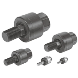
(i)Hinweis
- Bei Produktbildern kann es sich um repräsentative Bilder handeln. Einzelheiten finden Sie im Katalog.
Teilenummer
Hier finden Sie die Teilenummern
zu dem gesuchten Artikel
Floating Joint: Standard Type JA Series Specifications
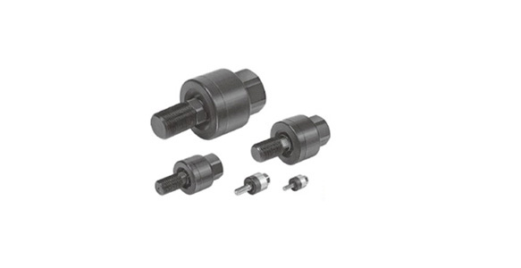
JA Series external appearance
- Operating pressure: Pneumatic cylinder: 1 MPa or less; Hydraulic cylinder: 3.5 MPa or less
- Mounting: basic type, flange type, foot type
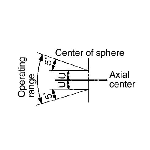
JA Series operating range
| Model | Compatible bore size (mm) | Compatible cylinder nominal thread size | Maximum operating tension and compression force N | Allowable eccentricity U (mm) | Rotating angle | Ambient temperature | ||
|---|---|---|---|---|---|---|---|---|
| Basic type | Flange type | Foot type | ||||||
| JA6-3-050 | 6 | M3 × 0.5 | 19 | - | - | 0.5 | ±5 ° | -5 to 60°C |
| JA10-4-070 | 10 | M4 × 0.7 | 54 | - | - | 0.5 | ||
| JA15-5-080 | 10, 15 | M5 × 0.8 | 123 | - | - | 0.5 | ||
| JA15-6-100 | 15 | M6 × 1 | 123 | - | - | 0.5 | ||
| JA□20-8-125 | 20 | M8 × 1.25 | 1,100 | 1,100 | 1,000 | 0.5 | ||
| JA□30-10-125 | 25/32 | M10 × 1.25 | 2,500 | 2,500 | 2,000 | 0.5 | ||
| JA□40-14-150 | 40 | M14 × 1.5 | 4,400 | 4,400 | 4,400 | 0.75 | ||
| JA□63-18-150 | 50/63 | M18 × 1.5 | 11,000 | 11,000 | 9,000 | 1 | ||
| JA□80-22-150 | 80 | M22 × 1.5 | 18,000 | 18,000 | 14,000 | 1.25 | ||
| JA□100-26-150 | 100 | M26 × 1.5 | 28,000 | 28,000 | 22,000 | 2 | ||
| JA□140-30-150 | 125/140 | M30 × 1.5 | 54,000 | 36,000 | 36,000 | 2.5 | ||
| JA□160-36-150 | 160 | M36 × 1.5 | 71,000 | 55,000 | 55,000 | 3 | ||
| JA□20-8-100 | 20 | M8 × 1 | 1,100 | 1,100 | 1,000 | 0.5 | ±5 ° | |
| JA□25-10-150 | 25 | M10 × 1.5 | 2,500 | 2,500 | 2,000 | 0.5 | ||
| JA□32-10-100 | 32 | M10 × 1 | 2,500 | 2,500 | 2,000 | 0.5 | ||
| JA□40-12-125 | 32/40 | M12 × 1.25 | 4,400 | 4,400 | 4,400 | 0.75 | ||
| JA□40-12-150 | 40 | M12 × 1.5 | 4,400 | 4,400 | 4,400 | 0.75 | ||
| JA□40-12-175 | 32/40 | M12 × 1.75 | 4,400 | 4,400 | 4,400 | 0.75 | ||
| JA□50-16-150 | 50 | M16 × 1.5 | 11,000 | 11,000 | 9,000 | 1 | ||
| JA□63-16-200 | 50/63 | M16 × 2 | 11,000 | 11,000 | 9,000 | 1 | ||
| JA□80-20-250 | 80 | M20 × 2.5 | 18,000 | 18,000 | 14,000 | 1.25 | ||
| JA□100-24-300 | 100 | M24 × 3 | 28,000 | 28,000 | 22,000 | 2 | ||
| JA□100-27-150 | 100 | M27 × 1.5 | 28,000 | 28,000 | 22,000 | 2 | ||
| JA□125-27-200 | 125 | M27 × 2 | 28,000 | 28,000 | 28,000 | 2 | ||
| JA□160-33-200 | 160 | M33 × 2 | 71,000 | 55,000 | 55,000 | 3 | ||
Diagram / Parts List
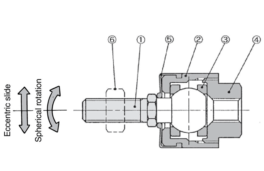
ø6 to 15 (diameter 6 to 15 mm) diagram
*See the manufacturer's catalog regarding replacement parts.
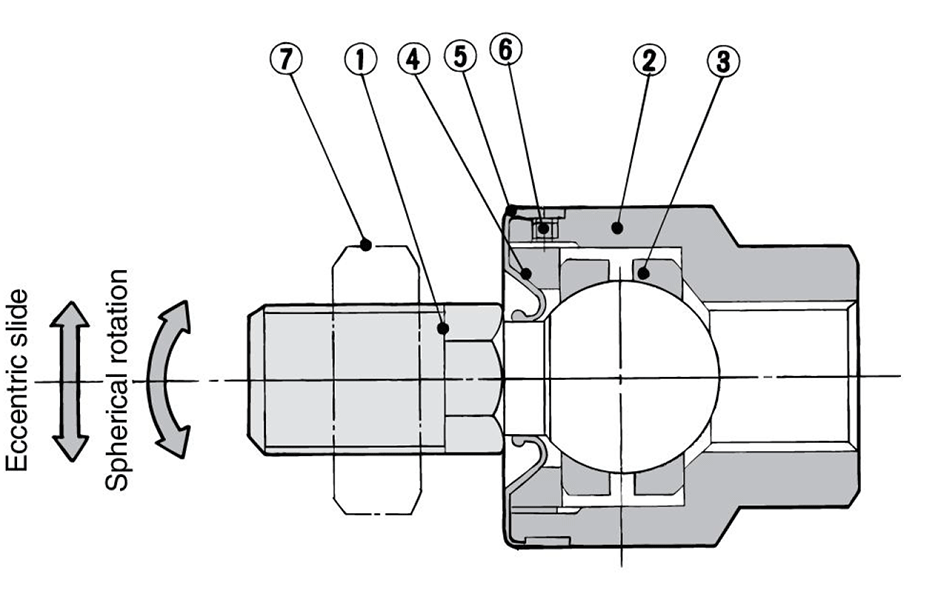
ø20 to 160 (diameter 20 to 160 mm) diagram
| Number | Description | Material | Note |
|---|---|---|---|
| 1 | Stud | Free-cutting steel | Electroless nickel plated |
| 2 | Case | Brass | Electroless nickel plated |
| 3 | Ring | Stainless steel | - |
| 4 | Socket | Brass | Electroless nickel plated |
| 5 | Dust cover | Synthetic rubber | - |
| 6 | Rod end nut | Low carbon steel wire rod | Zinc chromated |
| Number | Description | Material | Note |
|---|---|---|---|
| 1 | Stud | Chrome molybdenum steel | Dyed black |
| 2 | Case | Carbon steel | Black zinc chromated |
| 3 | Ring | Chrome molybdenum steel | - |
| 4 | Cap | Carbon steel | Black zinc chromated |
| 5 | Dust cover | Synthetic rubber | - |
| 6 | Set screw | Carbon steel | Zinc chromated |
| 7 | Rod end nut | Carbon steel | Zinc chromated |
| 8 | Flange | Rolled steel | Black zinc chromated |
| 9 | Foot | Rolled steel | Black zinc chromated |
Precautions
Mounting
- *When screwing the male threads of the rod into the female threads of the socket or the case, make sure that the rod does not bottom out. If the floating joint is used with its rod bottomed out, the stud will not be able to float, causing damage. For the screw-in depth of the female threads, refer to the dimensions in the manufacturer's catalog. As a rule, after the rod bottoms out, back off 1 to 2 turns.
- *The dust cover may stick to the stud. Move the dust cover at the base of the stud with your fingers, or twist the stud right and left gently to free it. When screwing the stud and socket or case into a driven body, make sure to remove the dust cover. Screwing without removing dust cover may break the dust cover.
- *When using a floating joint to connect the cylinder rod to a driven body, secure it in place by applying a torque that is appropriate for the thread size. Also, if there is a risk of loosening during operation, take measures to prevent loosening, such as using a locking pin or thread adhesive. In the event that the connected portion becomes loose, the driven body might lose control or fall off, etc., leading to equipment damage or injury to personnel.
- *This product is not a rotary joint. It cannot be used for rotational applications.
- *Be sure to use the cushion mechanism of the cylinder or a buffer mechanism such as a shock absorber to prevent impact force being applied to the floating joint when stopping the driven body. If there is no buffer mechanism, an impact force is generated that may cause the floating joint to exceed its maximum tensile and compressive force level.
Maintenance
- *Do not use if the product has been disassembled. High-strength adhesive is applied to the portion of the connection that is threaded to prevent it from loosening. The product must therefore not be disassembled. If the product is forcefully disassembled, it could lead to damage.
- *Black zinc chromate treatment is applied to the material surfaces of the case, flange and foot. In rare circumstances, white deposits may occur on the surface.
Other precautions
- *See the manufacturer's catalog for information other than the above.
- *Pictures are of representational models.
Teilenummer
|
|---|
| JA80-20-250 |
| JA80-22-150 |
| JA80-22-150-X11 |
| JAF80-20-250 |
| JAF80-22-150 |
| JAL80-20-250 |
| JAL80-22-150 |
| Teilenummer |
Standard-Stückpreis
| Mindestbestellmenge | Mengenrabatt | [M] Durchmesser (nominal) Anschlussgewinde (mm) | [p] Durchmesser (nominal) Anschlussgewinde (mm) | Montagemethode (aktive Seite) | Werkstoff (Korpus) | Montagemethode (passive Seite) | Werkstoff (Bolzen) | [U] Fehlstellung (zul.) (mm) | Geeignete Zylinder-Bohrungsgröße (ø) | Geeignetes Zylinder-Nenngewinde | Option | |
|---|---|---|---|---|---|---|---|---|---|---|---|---|---|---|
72.52 € | 1 | 4 Arbeitstage | M20 bis M26 | 2 bis 2.5 | rund, Außengewinde | [Stahl] Karbonstahl | axiales Gewinde | [Stahl] Chrom-Molybdän-Stahl | 1,25 | 80 | M20 × 2,5 | Ohne | ||
76.06 € | 1 | 4 Arbeitstage | M20 bis M26 | 1 bis 1.75 | rund, Außengewinde | [Stahl] Karbonstahl | axiales Gewinde | [Stahl] Chrom-Molybdän-Stahl | 1,25 | 80 | M22 × 1,5 | Ohne | ||
87.60 € | 1 | 98 Arbeitstage | M20 bis M26 | 1 bis 1.75 | rund, Außengewinde | [Stahl] Karbonstahl | axiales Gewinde | [Stahl] Chrom-Molybdän-Stahl | 1,25 | 80 | M22 × 1,5 | Hochtemperaturspezifikationen (-5 bis + 100 °C) | ||
91.52 € | 1 | 26 Arbeitstage | M20 bis M26 | 2 bis 2.5 | Bohrung | [Stahl] Karbonstahl | Stirnflansch | [Stahl] Chrom-Molybdän-Stahl | 1,25 | 80 | M20 × 2,5 | Ohne | ||
94.65 € | 1 | 4 Arbeitstage | M20 bis M26 | 1 bis 1.75 | Bohrung | [Stahl] Karbonstahl | Stirnflansch | [Stahl] Chrom-Molybdän-Stahl | 1,25 | 80 | M22 × 1,5 | Ohne | ||
88.50 € | 1 | 26 Arbeitstage | M20 bis M26 | 2 bis 2.5 | Bohrung | [Stahl] Karbonstahl | L-Fuß | [Stahl] Chrom-Molybdän-Stahl | 1,25 | 80 | M20 × 2,5 | Ohne | ||
94.65 € | 1 | 26 Arbeitstage | M20 bis M26 | 1 bis 1.75 | Bohrung | [Stahl] Karbonstahl | L-Fuß | [Stahl] Chrom-Molybdän-Stahl | 1,25 | 80 | M22 × 1,5 | Ohne |
Loading...
Grundlegende Informationen
| Ausführung (Bauart) | Kupplungsset | Einsatzbereich (Zylinder) | Luftzylinder / Hydraulikzylinder | Ausführung (Zylinderseite) | rund, Innengewinde |
|---|---|---|---|---|---|
| [V] Winkelversatz (zul.)(°) | ±5 |
Konfigurieren
Basiseigenschaften
-
[M] Durchmesser (nominal) Anschlussgewinde(mm)
-
[p] Durchmesser (nominal) Anschlussgewinde(mm)
- 0.5 bis 0.8
- 1 bis 1.75
- 2 bis 2.5
- 2.5 oder höher
-
Montagemethode (aktive Seite)
-
 rund, Außengewinde
 -
 Bohrung
-
-
Werkstoff (Korpus)
- Stahl
- Messing
- Stahl
-
Montagemethode (passive Seite)
-
 axiales Gewinde
 -
 Stirnflansch
 -
 L-Fuß
L-Fuß
-
-
Werkstoff (Bolzen)
- Stahl
- Stahl
-
Geeignete Zylinder-Bohrungsgröße(ø)
- 6
- 10
- 15
- 20
- 25
- 30
- 32
- 40
- 50
- 63
- 80
- 100
- 125
- 140
- 160
-
Geeignetes Zylinder-Nenngewinde
- M3 × 0,5
- M4 × 0,7
- M5 × 0,8
- M6 × 1
- M8 × 1
- M8 × 1,25
- M10 × 1
- M10 × 1,5
- M10 × 1,25
- M12 × 1,25
- M12 × 1,75
- M12 × 1.5
- M14 × 1,5
- M16 × 1,5
- M16 × 2
- M18 × 1,5
- M20 × 2,5
- M22 × 1,5
- M24 × 3
- M26 × 1,5
- M27 × 1.5
- M27 × 2
- M30 × 1,5
- M33 × 2
- M36 × 1,5
-
Option
- Hochtemperaturspezifikationen (-5 bis + 100 °C)
- Ohne
-
Ausführung
-
[U] Fehlstellung (zul.)(mm)
-
Filtern nach CAD Format
- 2D
- 3D
Filtern nach vsl. Lieferzeit
-
- Alle Produkte
- Versand am selben Tag
- 3 Tage oder weniger
- 4 Tage oder weniger
- 7 Tage oder weniger
- 13 Tage oder weniger
- 22 Tage oder weniger
- 24 Tage oder weniger
- 26 Tage oder weniger
- 68 Tage oder weniger
- 98 Tage oder weniger
Optionale Eigenschaften
- Product images may be representative images. Refer to the catalog for details.
- Die Spezifikationen und Maße einiger Teile sind evtl. nicht vollständig enthalten. Genaue Details siehe Herstellerkataloge .


