ENTLÜFTUNGSEINSATZ MIT DURCHLÄSSIGER STRUKTUR (PRVT20-A50-B50-T50)

Produktdetails:
Hersteller-Teilenummer: PRVT20-A50-B50-T50
Marke: MISUMI
Preis: 158.19 €
Lieferzeit: 5 Arbeitstage
Technische Daten:
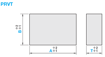
A (Vertikal): 50 mm
B (Horizontal): 50 mm
T (Höhe): 50 mm
- Bestellmengen erweitert (D-JIT)
Teilenummer
Hier finden Sie die Teilenummern
zu dem gesuchten Artikel
PRVT20-A50-B50-T50
- Zeichnung
- 3D-Vorschau Die 3D-Vorschau ist nach vollständiger Konfiguration verfügbar
- Teilenummern
- Weitere Informationen
- Katalog
Zeichnung / Produktspezifikation

Alle Seiten bearbeitet - ohne Belüftungsschlitze
Material: Rostfreier Stahl (1.4016 oder äquivalent)
Härte: 400 bis 450 HV
Auswahltabelle
| Referenzdaten | Artikelnummer | A | B | T | ||||||||
|---|---|---|---|---|---|---|---|---|---|---|---|---|
| Dichte (g/cm3) | Zugfestigkeit (MPa) | Wärmeleitfähigkeit (W/m・K) | Linearer Ausdehnungskoeffizient (10-6/℃) | Ausführung | Porendurchmesser (μm) | |||||||
| 6,1~6,4 | 450~480 | 10-11 | 12-12,5 | PRVT | 20 | 50 | 50 | 75 | 50 | |||
| 100 | 50 | 75 | 100 | 50 | ||||||||
| 150 | 100 | 100 | ||||||||||
| 200 | 50 | 100 | ||||||||||
| 300 | 100 | 50 | 100 | |||||||||
| 200 | 50 | |||||||||||
Bestellung


Teilenummer:
- Um die 3D Vorschau anzeigen zu können, muss die Konfiguration abgeschlossen sein.
3D Vorschau nicht verfügbar, da noch keine Teilenummer generiert wurde.
Teilenummer
|
|---|
| PRVT20-A50-B50-T50 |
| Teilenummer |
Standard-Stückpreis
| Mindestbestellmenge | Mengenrabatt | A (Vertikal) (mm) | B (Horizontal) (mm) | T (Höhe) (mm) | |
|---|---|---|---|---|---|---|---|
158.19 € | 1 | 5 Arbeitstage | 50 | 50 | 50 |
Loading...
Related Information

Avoid using for the exterior parts of mirror finished products
or transparent items.

■ How to Mount
1. Machine the POROUS VENT to match the shape of the molded part. Refer to the left page for treatment after machining.
2. Machine mounting holes and gas release passage into the mold. Be sure to clean with compressed air when finished to make sure that no particles remain, as they may cause clogging.
3. If you need to tap the POROUS VENT during installation, use a strike plate to ensure that the vents do not collapse.
4. When checking the ventilation, apply acetone or alcohol to the surface of the molded product and blow from the opposite side. If bubbles emerge from the entire surface, the product is normal.
■ For Use
· Ventilation recovery processing is necessary after shipment, as all surfaces are non-ventilated.
· Shave the rear surface to secure ventilation by making sure the POROUS VENT walls are not too thick.
· Grinding should be done so as to avoid ventilating the surface, other than for gas release.
· Periodic maintenance is required. Refer to the methods on the left page.
· For cooling, consider using a heat exchanger pipe (WHP) to avoid cooling water flowing directly through the water hole if water leaks. In that case, it is more effective to apply 0.05 to 0.1 mm heat conducting grease (MTJ) between the POROUS VENT and the cooling parts.
· Avoid installation of ejector pins, fixing pins, or inserted items on the POROUS VENT. When gas and air pass through the protruding holes, exhaust and blowing from the gas release holes may become insufficient, causing the released gas and air to return from the protruding holes to the molding surface and cause visual defects on the surface around the pin.
· To prevent rusting, do not store in high-temperature/high-humidity environments or those with fine dust.
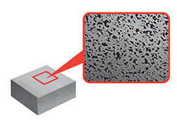
■ Features · A porous metal block insert blank developed for gas release applications. · The product has a porous structure made from sintered stainless steel (SUS430 equivalent). · Effective for improving the molded products surface. · Gas can be released from any direction, making the product suitable for molded articles with complex shapes, or for evenly releasing gas from wide-area parts. · Mechanical machining and laser machining can be performed as necessary for the shape of the molded product. |
|
■ Examples of Molding | ||
| • Product: Plastic case • Resin: PP • Application effects: Eliminates short shots between ribs and vertical walls |
■ Examples of Machining Conditions
[Table 1] shows an NC milling example while[Table 2] shows a laser machining example.
Check your specific equipment, as other machining methods differ depending on the equipment.
| [Table 1] Example of NC milling conditions | |
| Cutting speed (m/min) | 150 |
|---|---|
| Revolution (rpm) | 3000 |
| Axial cutting depth (mm) | 0.1 |
| Radial cutting depth (mm) | 0.25 |
| Feed (mm/revolution) | 0.16 |
| [Table 2] Example of laser machining conditions (depth 0.01 mm) | |
| Laser output (W) | 9 |
|---|---|
| Pulse frequency (kHz) | 30 |
| Feed speed (mm/sec) | 800 |
| Wavelength (nm) | 1064 |
| Offset (mm) | 0.01 |
· Material: Carbide + AlTiN coating
· Type: 4-flute radius R3
· Applicable work material: Stainless steel (M grade)
■ Post-Machining Treatment
• Oil draining
Always drain the oil for discharge machining, wire cutting, NC milling, etc., as impregnation with machining fluid can cause ventilation failure and rust. Refer to [Table 3] for differences in ventilation with and without oil drainage.
• Polished finishing
Finish according to the following procedure.
(1) Polish once with a fine (#800 recommended) oil stone, then rotate 90°and polish a second time.
(2) Polish with an ultra-fine (#1200 recommended) oil stone. (3) Buff using a paste-type polishing agent (0.5 to 1 μm particle size recommended).If necessary, use even finer sandpaper (#2500) to polish further.
| [Table 3] Ventilation by machining method (example) | |||
| Final machining method | Ventilation (ℓ/min・cm2) | ||
|---|---|---|---|
| No oil drainage | With oil drainage | ||
| Electric discharge / wire cutting | 1.24 ~ 1.30 | 3.30 ~ 3.60 | |
| NC milling | 0.55 ~ 0.61 | 0.70 ~ 0.75 | |
| Laser | 3.30 ~ 3.60 ※ Oil drainage not required | ||
Machining conditions NC milling: [Table 1] Laser: [Table 2]
Measurement conditions · Test piece size: φ20 x 10 mm · Air pressure: 0.3 Mpa
■ Oil Drainage Method
| (1) Air blowing | (2) Ultrasonic cleaning as required) | (3) Hot water washing | (4) Drying | |||
| Make air blowing holes (※) on the side opposite the molded part surface, to enable compressed air (factory air equivalent) at about 0.5 MPa to be blown for 5 to 10 minutes, prior to wiping off dirt from the molded part surface with a rag. ※Substitution is possible if the POROUS VENT has gas release holes. | Use ultrasonic cleaning for about 30 minutes to 1 hour while heating to 50 to 60℃, using a water-soluble detergent for metals. | Soak in 50 to 60℃ hot water for 5 minutes before performing (1). Repeat until the water is no longer cloudy. | Dry in a drying oven kept at 150 to 160℃ for 1 to 2 hours. If a drying oven is unavailable, perform (1) until moisture is no longer released. (Approximately 1 to 2 hours) | |||
| ||||||
■ Maintenance Method
| • Daily maintenance (in molding machinery) | • Periodic maintenance (in molding machinery) | • Periodic maintenance (disassembled from molding machinery) | ||
| This method eliminates mild resin clogging. It is recommended at the completion of molding (or before beginning) every day. 1. Spray alcohol on the surface while still mounted to the mold and immediately wipe off with a cloth. Repeat this 1 or 2 times. 2. Wipe the surface with a cloth moistened with alcohol while blowing compressed air through the gas release hole. | This method eliminates medium resin clogging. It is recommended weekly. 1. Spray organic solvent on the surface while still mounted to the mold and immediately wipe off with a cloth. Repeat this 1 or 2 times. 2. Wipe the surface with a cloth moistened with organic solvent while blowing compressed air through the gas release hole. Acetone is the recommended organic solvent, but the most suitable solvent depends on the specific resin. Contact the resin manufacturer for details. | This method helps to loosen resin clogs that cannot be removed by daily or periodic maintenance. It is recommended while disassembled from the molding machinery. 1. Remove the POROUS VENT from the mold and immerse it in a solvent such as acetone for 12 to 24 hours. 2. Execute the "Oil draining method" steps (1), (3) and (4) in order. |
Sie befinden sich auf der Seite für ENTLÜFTUNGSEINSATZ MIT DURCHLÄSSIGER STRUKTUR, die Teilenummer ist PRVT20-A50-B50-T50.
Sie finden detaillierte Informationen über Spezifikation und Dimensionierung unter der Teilenummer PRVT20-A50-B50-T50.
Konfigurieren
Basiseigenschaften
-
Ausführung
- PRVT20
-
A (Vertikal)(mm)
- 50
- 100
- 150
- 300
-
B (Horizontal)(mm)
-
T (Höhe)(mm)
-
Filtern nach CAD Format
- 2D
- 3D
Filtern nach vsl. Lieferzeit
-
- Alle Produkte
- 5 Tage oder weniger
- 12 Tage oder weniger
- 15 Tage oder weniger
Optionale Eigenschaften
- Die Spezifikationen und Maße einiger Teile sind evtl. nicht vollständig enthalten. Genaue Details siehe Herstellerkataloge .
Produktvarianten
| Teilenummer |
|---|
| PRVT20-A100-B50-T50 |
| PRVT20-A100-B75-T50 |
| PRVT20-A150-B100-T100 |
| PRVT20-A150-B200-T100 |
| PRVT20-A150-B200-T50 |
| PRVT20-A50-B75-T50 |
| Teilenummer | Standard-Stückpreis | Mindestbestellmenge | Mengenrabatt | Reguläre Versanddauer ? | A (Vertikal) (mm) | B (Horizontal) (mm) | T (Höhe) (mm) |
|---|---|---|---|---|---|---|---|
304.16 € | 1 | 5 Arbeitstage | 100 | 50 | 50 | ||
450.05 € | 1 | 5 Arbeitstage | 100 | 75 | 50 | ||
1,762.85 € | 1 | 12 Arbeitstage | 150 | 100 | 100 | ||
3,513.33 € | 1 | 12 Arbeitstage | 150 | 200 | 100 | ||
1,500.00 € | 1 | 15 Arbeitstage | 150 | 200 | 50 | ||
231.25 € | 1 | 5 Arbeitstage | 50 | 75 | 50 |


